23
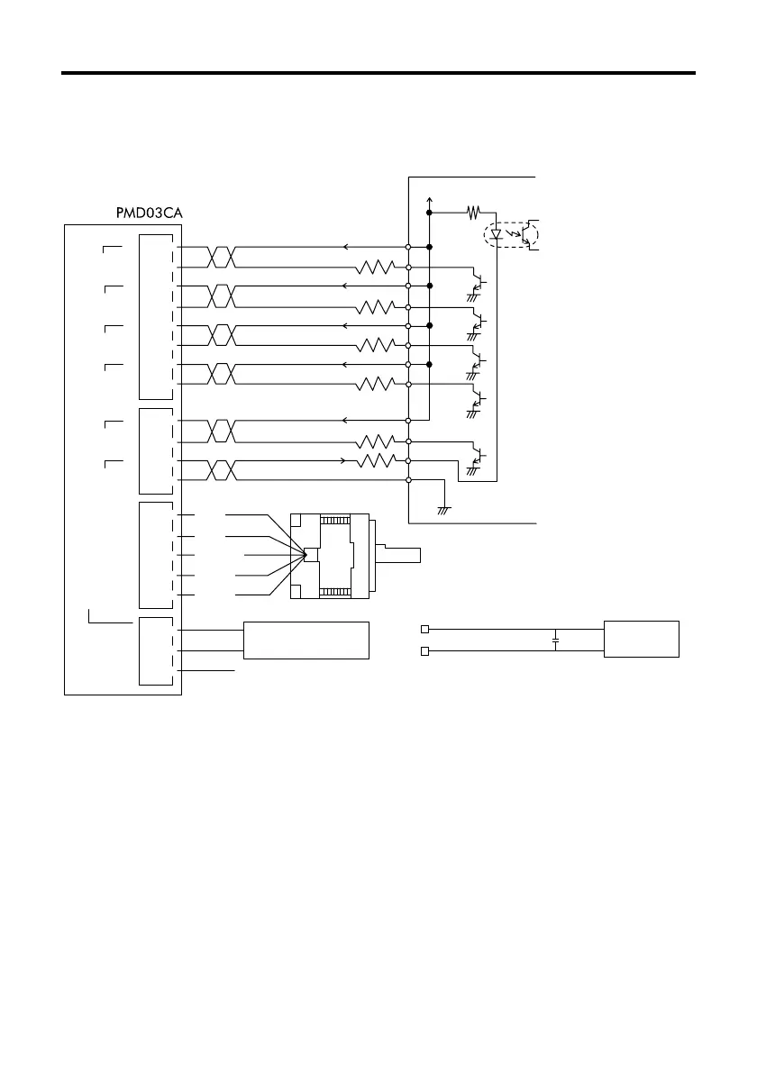
Example connections
Connection to user’s controller
+
-
N.C (power supply which is reinforced insulation)
GND
+24 / 36V
R
1
R
1
R
2
R
0
V
0
(+5V〜24V)
User’s controller
R
1
R
1
R
1
GND
SIGNAL1SIGNAL2MOTORPOWER
CW / P.
+
+
CCW / D.
+
C.OFF
+
F / H
+
C.UP
+
TIM
BLU
RED
ORG
GRN
BLK
+
24 / 36V
GND
NC
Driver( )
②
③
④
①
②
③
①
②
③
④
⑤
⑥
⑦
⑧
②
③
①
④
①
⑤
Pulse/CW pulse signal input
Rotation direction/
CCW pulse signal input
DC24V or DC36V
Power supply
Stepping motor
All windings off signal input
Step angle signal input
Automatic current cutback
release signal input
Excitation timing
Signal output
Blue
Red
Orange
Green
Black
DC POWER
SUPPLY
+
‑
+24V±10%
GND
Note: For operations involving sudden
deceleration or the driving of large
inertial loads, connect a capacitor
of 1000µF or more to suppress
the motor’s regenerative voltage.
Input signal connections
Keep the voltage between DC5V and DC24V.
When voltage is equal to DC5V, external resistance R
1
is not necessary.
When voltage is above DC5V, connect external resistance R
1
and keep the input
current below 20mA.
Output signal connections
Keep the voltage between DC5V and DC24V.
Keep the current below 10mA.
If the current exceeds 10mA, connect external resistance R
2
.
Turning on the power
Before turning the power ON, be sure that the signal lines, motor lead wires, power line,
and earth line are all properly connected.
The power LED lights when turning on the power (The power LED keeps lighting during
turning on the power.).