VR9500 Hardware Description
© 2019 Vibration Research Corporation is a registered trademark in the United States and other countries.
7
1.6 Cables, Port Connections, and Pinout Information
This section explains the switch physical interface and provides information about cables and port
connections.
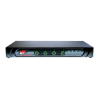
Front Panel LEDs
See the help file topic on how to read the front panel lights.
Rear Panel LEDs
Network status LEDs can be viewed through hole next to the network connector.
100BASE-T Cable Requirements
It is recommended that enhanced Category 5 (Category 5e) cable is used for all critical connections or any
new cable installations. The Category 5e specification includes test parameters that are only
recommendations for Category 5 and comply with the IEEE 802.3ab standards.
See also the RJ45 Connections topic.
BNC Inputs and Outputs
BNC connectors are manufactured with 50 and 75 ohm impedance capability. Fifty ohm cables are typically
used in this application. BNC Inputs are typically used with accelerometer. Nominal ranging allows for
maximum 20 volts peak input devices. BNC output ranging allows driving maximum 10V peak devices or
maximum 1V peak devices.
Aux Inputs/Outputs
See the help file topic on the EDZ950/20 Connector.
Power Connectors
The VR9500 is powered by using the AC internal power supply.
Internal Power Supply Connector
The VR9500 supports a single internal power supply to provide power for switching operations. The internal
power supply supports input voltages between 90 and 250 VAC. The AC power connector is located on the
back panel of the controller.
5
 Loading...
