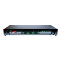
VR9500 Hardware Description
© 2019 Vibration Research Corporation is a registered trademark in the United States and other countries.
3
3. After connecting the device to a power source, confirm that the device is connected and operating
correctly by examining the LEDs on the front panel.
4. The supplied standard AC power cable is the primary disconnecting device. Do not to position the
equipment so that it is difficult to disconnect the AC power cord.
Connecting the Device to an Amplifier
CAUTION: Always connect the power cable to a grounded AC outlet prior to connecting or
disconnecting the drive cable.
1. Connect the supplied (or an alternative equivalent) 50 ohm BNC cable between the DRIVE output and the
DRIVE input on the amplifier.
Connecting the Device to the accelerometer
CAUTION: Always connect the power cable to a grounded AC outlet prior to connecting or
disconnecting the drive cable.
CAUTION: Always verify the mounting surface of the accelerometer is floating or grounded.
CAUTION Terminals provided on the unit shall be connected only to passive load transducers or
source transducers that apply no more than 10V to the circuit that originates from the VR9500 (or
other value that equates to not more than 33Vac RMS /46.7V peak or 70Vdc total on the circuit)
CAUTION Other than the IEC inlet for input power to the unit, terminals provided on the rear of
the unit shall be connected only to SELV / double insulated circuits of other equipment.
CAUTION If any sourcing transducers (accelerometer) add voltage to the existing voltage
originating from the VR9500 , the total shall not exceed the 70Vdc or 33 Vac(RMS).
Connect the accelerometer to the front panel input.
Connecting the Device to the Network
To connect to an uplink port, use Category 5 Unshielded Twisted-Pair (UTP) cables with RJ-45 connectors at
both ends. The RJ-45 ports on the Ethernet device support automatic Media-Dependent Interface/Media-
Dependent Interface with internal crossover wiring (MDI/MDIX) operation under Auto-Negotiation mode.
Standard straight-through twisted-pair cables can be used to connect to any other Ethernet network
(systems, servers, switches, or routers) that supports auto-negotiation.
NOTE: Do not plug a phone jack connector into an RJ-45 port. This will damage the Ethernet device. Use
only twisted-pair cables with RJ-45 connectors that conform to FCC standards.
To connect the device to the network:
1. Attach one end of a Twisted-Pair cable to the device's RJ-45 connector and the other end to a switch or
workstation computer.
2. Make sure the twisted pair cable does not exceed 328 feet (100 meters) in length.
As the connection is made, the network LED is illuminated, indicating that the connection is valid.
1.2 DB37 Connector
The DB37 mating connector is an Amphenol L777-RR-C-37-P (or equivalent).

 Loading...