Do you have a question about the VICI DBS NM PLUS Series and is the answer not in the manual?
Explains warning symbols and their meanings for safe operation of the hydrogen generator.
Details compliance with FCC rules for Class B digital devices and interference mitigation strategies.
Outlines proper use, environmental conditions, and water requirements for safe and effective generator operation.
Warns that unauthorized modifications can void user authority to operate the equipment.
Details the optional remote control capabilities via USB-RS232 and its pin configuration for external management.
Explains how to connect up to 10 generators in parallel using RS-485 for increased hydrogen output.
Describes the auto refill option for maintaining water levels from an external source, ensuring continuous operation.
Instructions for visual checks, damage reporting, and handling returns upon receipt of the unit.
Lists all items included in the generator shipment for verification against the packing list.
Guidelines for selecting a suitable location, ensuring ventilation, and avoiding hazards for optimal performance.
Details how to connect the hydrogen outlet port using specific tubing and connectors for gas output.
Instructions for checking and adjusting the voltage selector for proper electrical connection to the power source.
Step-by-step guide on how to fill the water tank with distilled or deionized water of the correct quality.
Instructions for placing deionizer bags in the water tank to maintain water purity for the electrolysis process.
Procedures for powering on, setting pressure, and initiating hydrogen production after initial setup.
Explains the main LCD display and its function in showing operational status and information.
Details the first row of the display, showing normal status, pre-alarms, and critical alarms.
Explains the second and third rows showing actual vs. set pressure and hydrogen flow rate.
Details the fourth row indicating water quality and explains the functions of control buttons.
Provides detail on pressure readings and hydrogen flow graph interpretation, including maximum capacity indicators.
Explains water quality interpretation and the operation of Start/Stop, Reset, and Exit buttons.
Illustrates the menu structure for accessing configuration, diagnostics, and utilities through the touch screen interface.
Details various parameters that can be configured, such as clock, pressure units, and temperature units.
Explains how to access diagnostic information like production totals and run system tests.
Describes special functions including system tests, hardware options, and troubleshooting aids.
Provides requirements and procedures for returning the generator for maintenance or repair, including safety and documentation.
Instructions for cleaning the outside of the unit using a damp cloth, avoiding harsh chemicals.
Guidance on when and how to refill the water tank with distilled or deionized water of the correct quality.
Recommends when to replace deionizer bags based on time intervals or water conductivity readings.
Detailed instructions for installing new deionizer bags in the water tank to maintain water purity for the electrolysis process.
Lists the components included in the maintenance kit for NM Plus generators, facilitating upkeep.
Presents the fluidic diagram and lists part numbers for various components, categorized by generator model and flow rate.
Shows the electrical schematic illustrating internal connections and lists part numbers for electrical components.
A detailed list of all available spare parts with their corresponding part numbers and descriptions for ordering replacements.
| Brand | VICI DBS |
|---|---|
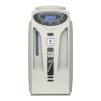
| Model | NM PLUS Series |
| Category | Portable Generator |
| Language | English |