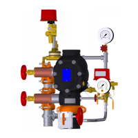
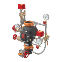
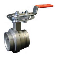
I-751.Europe / European Alarm Check Valve Stations / Installation, Maintenance, and Testing Manual
INITIAL SYSTEM SETUP
WARNING
• Series 751 FireLock
™
European Alarm Check Valve Stations and
supply piping shall be protected from freezing temperatures and
mechanical damage.
• For proper operation of alarms in a wet system, it is important to
remove all air from the system. Auxiliary drains may be required
to release all trapped air from the system.
• Alarms and electrical panels that are controlled by an alarm flow
switch on the riser shall not be interrupted. If alarm activation
is possible, notify local fire companies that the system is being
serviced.
Failure to follow these instructions could cause improper valve
oper ation, resulting in death or serious personal injury and property
damage
Step 1:
Open the system main drain valve (Item 9). Confirm that the system is
drained.
Step 2:
Close the system main drain valve (Item 9).
Step 3:
Confirm that system drains are shut and the system is free of leaks.
Step 3a:
Confirm that the system has been depressurized. The gauges should
indicate zero pressure.
Step 4:
Open the remote system test valve (inspector’s test connection) and any
auxiliary drains to remove all air from the system.
Step 5:
Close the alarm line ball valve (Item 13) to prevent alarms from
operating while the system is filling. FOR FG AND SBSC TRIM: Close
the alarm line monitoring ball valve(s)– Item 14a on page 7.
Step 6:
Open the water supply main control valve (Item 3) slowly. Allow the
system to fill with water completely. Allow water to flow from the remote
system test valve (inspector’s test connection) and any auxiliary drains
until all trapped air is removed from the system.
Step 7:
Close the remote system test valve (inspector’s test connection) and any
auxiliary drains. NOTE: The system pressure gauge (Item 7) reading
should be equal to or greater than the water supply pressure gauge
(Item 5) reading.
Step 8:
Open the water supply main control valve (Item 3) fully.
WARNING
• The alarm line ball valve or alarm line monitoring ball valve(s)
shall remain in the open position to allow alarms to activate.
Failure to follow this instruction will prevent alarms from activating,
resulting in death or serious personal injury and property damage.
Step 9:
Open the alarm line ball valve (Item 13). Lock the ball valve, if required.
FOR FG AND SBSC TRIM: Open the alarm line monitoring ball valve(s)–
Item 14a on page 7.
Step 10:
Confirm that all valves are in their normal operating positions (refer to
the table below).
Valve Normal Operating Position
Alarm Line Ball Valve (Lockable) Open
Water Supply Main Control Valve Open
System Main Drain Valve Closed
System Test Valve Closed
Alarm Line Monitoring Ball Valve(s) -
FG and SBSC Trim Only
Open
Step 11:
Notify the authority having jurisdiction, remote station alarm monitors,
and those in the affected area that the system is in service.
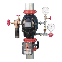
Water Supply Main
Control Valve
(Item 3, Steps 5 & 7)
Alarm Line
Ball Valve
(Item 13,
Steps 4 & 8)
System
Pressure Gauge
(Item 7, Step 6)
Water Supply
Pressure Gauge
(Item 5, Step 6)
VDS, CE, UKCA, FM, EAC VERSION SHOWN
I-751.Europe_10REV_G

 Loading...
