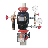
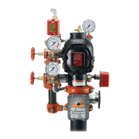
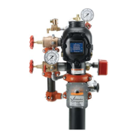
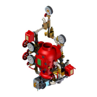
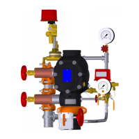
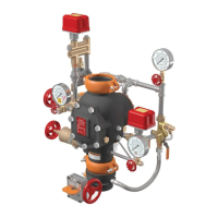
I-751.Europe / European Alarm Check Valve Stations / Installation, Maintenance, and Testing Manual
TABLE OF CONTENTS
Hazard Identification ......................................1
Installer Safety Information .................................1
Important Installation Information ............................2
Hydrostatic Testing
.......................................2
Receiving the Shipment
....................................2
Trim Assembly Drawing Numbers ............................2
European Trim Dimensions ..............................3 – 6
Trim Components
Exploded View Drawing . . . . . . . . . . . . . . . . . . . . . . . . . . . . . . . . . . 7
Internal Valve Components - Section View and
Exploded View Drawings .................................8
SECTION I
Initial System Setup ......................................10
SECTION II
Resetting the System
.....................................12
SECTION III
Inspection/Testing Requirements
............................14
SECTION IV
Required Main Drain Test .................................16
SECTION V
Required Water Flow Alarm Test ............................18
SECTION VI
Required Internal Inspection ...............................20
SECTION VII
Removing and Replacing the Clapper Seal (All Sizes).............22
Removing and Replacing the Clapper Assembly (All Sizes).........24
Installing the Cover Plate Gasket and Cover Plate................25
SECTION VIII
Troubleshooting .........................................26
HAZARD IDENTIFICATION
Definitions for identifying the various hazard levels are
provided below. When you see this symbol, be alert to
the possibility of personal injury. Carefully read and fully
u nderstand the message that follows.
WARNING
• The use of the word “WARNING” identifies the presence of
hazards or unsafe practices that could result in death or serious
personal injury and property damage if instructions are not
followed.
CAUTION
• The use of the word “CAUTION” identifies possible hazards or
unsafe practices that could result in personal injury and product
or property damage if instructions are not followed.
NOTICE
• The use of the word “NOTICE” identifies special instructions
that are important but not related to hazards.
INSTALLER SAFETY INFORMATION
WARNING
• An experienced, trained installer shall install this product in
accordance with all instructions. These i nstructions contain
important information.
• Depressurize and drain the piping system before attempting to
install, remove, adjust, or maintain any Victaulic piping products.
Failure to follow these instructions can cause product failure,
resulting in death or serious personal injury and property damage.
1. Read and understand all instructions and refer to the trim
diagrams before installing, maintaining, or testing a Victaulic
Series 751 FireLock
™
European Alarm Check Valve Station. For
proper operation and approval, the alarm valve and accessories
shall be installed in accordance with the specific trim diagrams
included with the shipment.
2. Use only recommended accessories. Accessories and equipment
that are not approved for use with this alarm valve may cause
improper system operation and property damage.
3. Wear safety glasses, hardhat, foot protection, and hearing
protection. Wear hearing protection if you are exposed to long
periods of noisy jobsite operations.
4. Prevent back injury. Valve assemblies require more than one
person (or mechanical lifting equipment) to position and install the
assembly. Always practice proper lifting techniques.
5. Keep work areas clean. Keep the work area clean and well lit, and
allow enough space to accommodate proper installation of the
valve, trim, and accessories.
6. Avoid pinch points. Due to the weight of the valve body, use
caution around pinch points and spring-loaded components
(i.e. clapper assembly) in order to prevent bodily injury.
I-751.Europe_1 REV_G

 Loading...
