REMOVING AND REPLACING THE DIAPHRAGM ASSEMBLY
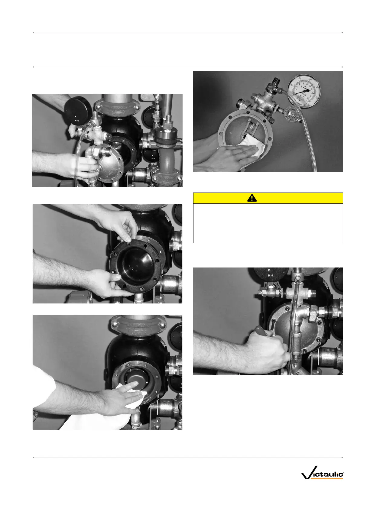
1. Break the unions that connect the trim to the diaphragm cover.
Refer to the applicable trim drawing for details.
2. Remove the cap screws from the diaphragm cover, and pull the
diaphragm cover/trim off the valve.
3. Remove the diaphragm from the valve body.
4. Clean the back of the valve body to remove any debris that may
interfere with proper diaphragm seating.
4a. Clean the inside of the diaphragm cover to remove any foreign
material.
CAUTION
Use caution when installing a new diaphragm into the valve •
body.
Failure to follow this instruction could cause damage to the
diaphragm, resulting in improper valve operation and valve
leakage.
5. Replace the diaphragm with a new, Victaulic-supplied diaphragm.
Align the holes in the diaphragm with the holes in the valve body.
Be careful not to damage the diaphragm during installation.
6. Align the holes of the diaphragm cover with the holes in the dia-
phragm/valve body. Tighten all cap screws into the diaphragm
cover/valve body.
7. Re-attach the trim at the unions that were loosened in step 1.
Refer to the applicable trim drawing for details. MAKE SURE
ALL UNIONS THAT WERE LOOSENED TO PERMIT ACCESS
TO THE DIAPHRAGM COVER ARE RE-TIGHTENED BEFORE
ATTEMPTING TO PLACE THE SYSTEM BACK IN SERVICE.
8. Place the system back in service by following the “Placing the
System in Service” section in the applicable installation, mainte-
nance, and testing manual for the valve configuration.
I-NXT.DIA_3
Series 764, 768 and 769
REPLACING THE DIAPHRAGM IN SERIES 764, 768, AND 769 FIRELOCK
NXT™ FIRE PROTECTION VALVES
I-NXT.DIAREPLACEMENT KIT INSTRUCTIONS
www.victaulic.com
VICTAULIC IS A REGISTERED TRADEMARK OF VICTAULIC COMPANY. © 2009 VICTAULIC COMPANY. ALL RIGHTS RESERVED. PRINTED IN THE USA.
REV_A

 Loading...


