EasyManua.ls Logo

Victron energy 24/5 User Manual

Victron energy 24/5
4 pages
To Next Page IconTo Next Page
Page #1 background imageLoading...
Page #1 background image
Manual Blue Power Charger XLR Class II Rev 01
U (V)
30
28
26
24
I (A)
8
6
4
2
0
bulk
absorption (max 8 h)
float
(max
24 h)
absorption (1 h)
28,8 V
28,0 V
storage
(1 week)
26,4 V
28,8 V
storage
(1 week)
Blue Power Charger
XLR Class II
24/5
24/8
Input voltage range
90-250 VAC
Frequency
45-65 Hz
Charge voltage 'absorption'
28,8 V
Charge voltage 'float'
28 V
Charge voltage 'storage'
26,4 V
Charge current (A)
5 A
8 A
Charge characteristic
4-stage adaptive
Recommended battery capacity
20 to 50 Ah
30 to 80 Ah
Protection
Battery reverse polarity
Output short circuit Over temperature
Operating temp. range
-20 to +60°C (full rated output up to 40°C)
Humidity (non condensing)
Max 95 %
ENCLOSURE
Material & Colour
ABS (blue RAL 5012)
Battery-connection
Cable of 1,5m with male XLR connector
230 V AC-connection
Cable of 2m with class II “Euro”plug (CE 7/16)
Protection category
IP 21, Class II
Weight
1,34 kg
Dimensions (L x W x H)
232 x 94 x 64 mm
STANDARDS
Safety
EN60335-1, EN60335-2-29, EN12184, ISO7176-14
Emission
EN60601-1-2, EN61000-3-2, EN61000-3-3,
EN61000-6-3, EN55022, EN55014-1
Immunity
EN60601-1-2, EN61000-6-2, EN55024, EN55014-2
Question and Answer IconNeed help?

Do you have a question about the Victron energy 24/5 and is the answer not in the manual?

Victron energy 24/5 Specifications

General IconGeneral
Input Voltage230 VAC
Output Voltage24 VDC
Output Current5 A
Battery Voltage24 V
Input Frequency45-65 Hz
Efficiency85%
ProtectionOver temperature protection
Operating Temperature-20°C to +60°C

Summary

State of the Art Microprocessor Controlled Charge Algorithm

Variable Absorption Time for Optimal Charging

Optimizes absorption time based on battery discharge depth to prevent overcharging.

Storage Mode for Reduced Maintenance

Reduces voltage and periodically equalizes to minimize corrosion and gassing.

Safety Regulations and Measures

Adhere to Installation Instructions

Follow installation guidelines carefully to ensure safe operation and prevent hazards.

Avoid Explosive Environments

Avoid use in potentially explosive environments due to gas or dust presence.

Comply with Local Regulations

Ensure all connections and safety measures comply with local regulations.

Replace Damaged Power Cords

Damaged power cords require immediate replacement by qualified personnel.

Do Not Charge Non-Rechargeable Batteries

Never attempt to charge non-rechargeable batteries as it can be hazardous.

Installation and Instructions for Use

Proper Installation Location

Install charger in a well-ventilated area, not directly above the battery.

Connect DC Cable

Connect the charger using the provided XLR charging connector to the battery.

Connect AC Mains Cable

Connect the AC power cable to the wall socket to start the charging cycle.

Normal Operation Temperature

The charger housing may become warm during operation, which is normal.

LED Indication

Green LED Status

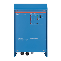
Indicates the charger is connected to AC power.

Yellow LED Status

Indicates that the battery is currently charging.

Yellow LED Off Status

Shows charging is complete or the XLR connector is disconnected.

Battery Instructions

Avoid Complete Battery Discharge

Avoid complete battery discharge to prevent damage.

Prompt Recharging for Longevity

Recharge batteries promptly after use, even with slight discharge, for longer life.

Maintenance for Infrequently Used Batteries

Charge infrequently used batteries monthly or keep connected for optimal condition.

Related product manuals