Do you have a question about the Victron energy MultiPlus 24/5000/120 and is the answer not in the manual?
| Brand | Victron energy |
|---|---|
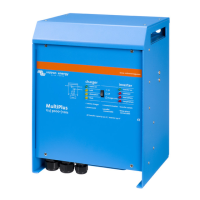
| Model | MultiPlus 24/5000/120 |
| Category | Battery Charger |
| Language | English |
General safety advice and product usage guidelines.
Instructions and precautions for installing the product safely.
Manages shore/generator current and supplements with battery power.
Details the adaptive charging process.
Guidance on choosing a suitable installation location.
Instructions for connecting battery cables.
How to connect the AC input cable.
How to connect the main AC output cable.
How to connect the auxiliary AC output cable.
Requirements for parallel and three-phase configurations.
Factory default settings for single-unit operation.
Explanation of various configuration settings.
First step of DIP switch configuration.
Setting AC input current limits via DIP switches.
Setting the AES mode using DIP switches.
Setting battery charge current via DIP switches.
Selecting stand-alone, parallel, or 3-phase operation.
Common problems, causes, and solutions.
Error codes for VE.Bus system status.