66250457-EN - V5.1 - 31/08/20
- 9 -
VK4K/6256 Series “6 wire Bus” videokit
VK4K/6256 Series - Installation handbook
Art.4833/4833X Speaker unit
SETTINGS
4 WAY DIPSWITCH
First two switches are used to set the speaker unit address: the speaker unit address is required for camera recall operation on 2 or
more entrance systems.
UNIT ADDRESS
Switch Nr.1 Nr.2 Setting up
ON
1 32 4
OFF OFF = 1
ON
1 32 4
ON OFF = 2
ON
1 32 4
OFF ON = 3
ON
1 32 4
ON ON = 4
CONVERSATION TIME
Switch Nr.3 Setting up
ON
1 32 4
OFF = 60 seconds
ON
1 32 4
ON = 120 seconds
DOOR OPENING TIME
J2 = “L” POSITION
Switch Nr.4 Setting up
ON
1 32 4
OFF = 2 seconds
ON
1 32 4
ON = 6 seconds
JUMPERS
J1 CALL REASSURANCE
TONE VOLUME
Jumper Setting up
H
L
J1 J2 J3 J4
High
H
L
J1
J2 J3 J4
Low
J2 DOOR OPEN RELAY
OPERATING MODE
Jumper Setting up
H
L
J1 J2 J3 J4
Capacitor
discharge
H
L
J1 J2 J3 J4
Dry contacts
J3 CALL BUTTONS
OPERATING MODE
ONLY FOR ART.4833
Jumper Setting up
H
L
J1 J2 J3 J4
Both buttons call
the same video-
phone (Address 1)
H
L
J1 J2 J3 J4
Each button
calls a dierent
videophone
J4 BUILTIN RELAY BACK
EMF PROTECTION MOV
Jumper Setting up
H
L
J1 J2 J3 J4
NC contact
H
L
J1 J2 J3 J4
NO contact
BUILTIN RELAY BACK EMF PROTECTION
The Art.4833 includes selectable back EMF protection on the relay. The jumpers marked J4 is used to select the protection type.
When using a fail secure lock with connections C & NO the jumper should be in the NO position. When using a fail open lock with
connections C & NC the jumper should be in the NC position and when used to trigger a gate controller or another third party con-
troller the jumper should be removed completely (This disables the protection on the relay).
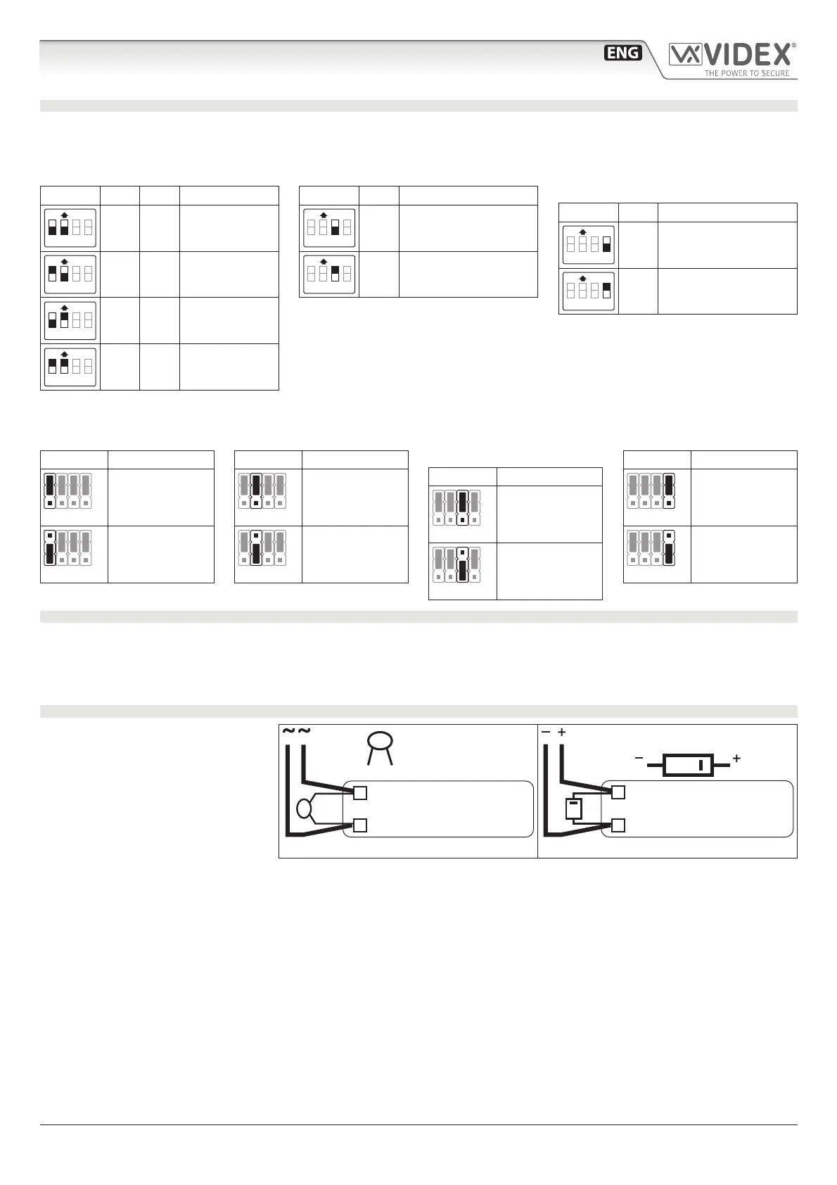
LOCK RELEASE BACK EMF PROTECTION
A varistor must be tted across the ter-
minals on AC lock release (Fig. 3) and
a diode must be tted across the ter-
minals on a DC lock release (Fig. 4) to
suppress back EMF voltages. Connect
the components to the lock releases as
shown in gures.
VARISTOR MOV
12V AC
LOCK RELEASE
Fig. 3
DIODE 1N4002
12V DC
LOCK RELEASE
Fig. 4
 Loading...