EasyManua.ls Logo

Videx GSM Lite 4000 Series User Manual

Videx GSM Lite 4000 Series
52 pages
To Next Page IconTo Next Page
Page #1 background imageLoading...
Page #1 background image
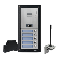
GSM LITE AUDIO INTERCOM KIT
4000 Series GSM Lite Audio Intercom
66250756-EN
V2.1 - 05/11/19
We recommend
This equipment is installed by a
Competent Electrician, Security or
Communications Engineer.
Technical Manual
ENG
LTGSM4K
LTGSM4KC

Questions and Answers:

Videx GSM Lite 4000 Series Specifications

General IconGeneral
BrandVidex
ModelGSM Lite 4000 Series
CategoryIntercom System
LanguageEnglish

Summary

Introduction

Manual Introduction

Information for installation and commissioning guide for the GSM LITE audio intercom system.

System Introduction

System designed for mobile phone technology, enabling calls from entry points to telephone numbers.

SIM Card Selection

Details on the required SIM card size and recommendations for selection.

Network Provider Selection

Importance of selecting the best network provider for reliable operation.

System Components and Available Versions

Description

Overview of system components including intercom panel, power supply, SIM card, and antenna.

Art. 4811 GSM (Lite) Intercom Available Versions

Details on different configurations of the Art. 4811 GSM (Lite) intercom module.

4000 Series Back Boxes and Mounting Frames

Information on flush and surface back boxes and mounting frames for the 4000 series.

12VDC 2A Power Supply (HDR-15-12)

Technical specifications and compatibility of the HDR-15-12 power supply.

Art. 432 GSM Antenna

Details on the Art. 432 GSM antenna, its parts, and connection.

Art. 4901 Codelock

Information about the Art. 4901 codelock module, its features, and power.

GSM Intercom Audio Kits

Overview of different GSM Intercom Audio Kits, their components, and versions.

Art. 4811 Technical Information

Art. 4811 GSM (Lite) Module

Diagram and labels for the Art. 4811 GSM (Lite) module.

Speaker Volume Adjustment (Dip-Switch Settings)

How to adjust speaker volume using dip-switches on the module.

Nameplate Illumination Jumper JP2

Explanation of the JP2 jumper for nameplate LED illumination adjustment.

Terminal Connections

Description of terminals on the Art. 4811 module and their functions.

Technical Specification

Detailed technical specifications for the Art. 4811 GSM LITE module.

Art. 4901 Technical Information

Art. 4901 Codelock Module

Diagram and labels for the Art. 4901 codelock module.

Description

Features of the codelock module, including buttons, LEDs, relays, and inputs.

Relay Built-in Back EMF Protection Jumpers

Information on MOV jumpers for back EMF protection on relays.

Programming the Keypad

How to program the codelock keypad using the engineer's code.

Back Light and Button Operation

How backlight and buttons operate based on mode and jumper settings.

Operation

How to use the codelock by entering access codes.

Programming Guide

Step-by-step guide for programming the codelock keypad.

Return System to Preset Engineer's Factory Code

Procedure to reset the engineer's code to the factory default.

Technical Specification

Technical specifications for the Art. 4901 codelock module.

Wiring Diagrams

LTGSM4K Connections

Wiring diagram for LTGSM4K with fail secure lock release.

Connecting a Push to Exit Button and a Break Glass Unit

Wiring diagram for push to exit button and break glass unit.

LTGSM4KC Connections

Wiring diagram for LTGSM4KC with fail secure/safe lock release and gate controls.

Auxiliary Inputs/Outputs

Auxiliary Output AO1

Overview of auxiliary output AO1 and its six modes.

AO1 Set to Mode 00, 'Call Activated'

How AO1 activates when a call begins and deactivates when it ends.

AO1 Set to Mode 01, 'User Activated'

How AO1 activates via terminals or button press for a programmed time.

AO1 Set to Mode 02, 'Status Indication'

Using AO1 as a monitoring input to check gate/door status.

AO1 Set to Mode 03, 'Divert Calls to Master Number'

Using AO1 to divert calls to a master number based on a switched input.

AO1 Set to Mode 04, 'Call Activated (Timed)'

How AO1 activates during a call and deactivates after a set time.

AO1 Set to Mode 05, 'Enable/Disable Dial to Open Numbers'

Using AO1 to enable/disable dial to open numbers via a switch.

Auxiliary Input 2

How auxiliary input 2 sends an SMS message to the master number.

General Directions for Installation

Cable Size Guide

Guide for selecting appropriate cable sizes for power supply and lock release.

General Installation Notes

General notes for safe and correct installation.

Lock Release Wiring and Back EMF Protection

Wiring and back EMF protection for electric lock releases.

Connection to Mains, Safety and Guidance Notes

Safety instructions and guidance for connecting to the mains supply.

Power Supply Installation

Steps for installing the HDR-15-12 power supply.

Panel Care

Instructions on how to clean and maintain the door panel fascia.

Fitting the SIM & Connecting Power

Fitting the SIM Card and Connecting the Power to the GSM Intercom

Steps for installing the SIM card and connecting power before powering up.

Power Up Initialisation Sequence

The process the GSM LITE module undergoes to initialise after power up.

Reset Procedure

Resetting the GSM Module to Factory Defaults

Overview of the two hard-wired reset options available.

Full System Reset

Procedure to reset all settings and stored telephone numbers to factory defaults.

4000 Series Back Box Installation

Example: Installing a 4000 Series Four Module Back Box

Step-by-step guide for installing a four-module back box.

Installing a Surface Mount Door Station

Detailed steps for installing a surface mount door station.

Installing a Flush Mounting Door Station

Steps for installing a flush mounting door station, including linking back boxes.

How to Remove the Card Name Holder

Instructions for removing and refitting the card name holder.

Programming the GSM Intercom

Programming by Text Message

Format for sending SMS programming commands to the module.

4 Digit Code

Explanation of the 4-digit access code for programming.

3 Digit Function Code

Table of available 3-digit function codes for programming.

Storing the Call Button Telephone Numbers (STN and STD)

How to store primary and divert telephone numbers for call buttons via SMS.

Storing the Primary and Divert Number in a Single Text Message (Using STN)

Programming primary and divert numbers in one SMS message.

Storing a Dial to Open Number (STR)

How to store numbers for the dial to open (DTO) feature.

Storing Up to 5 Dial to Open Numbers in a Single Text Message

Storing multiple DTO numbers in a single SMS message.

Delete a Dial to Open Number Without Knowing It's Location (DET)

How to delete a DTO number if its location is unknown.

Set Call Time (SPT)

How to set the maximum call duration via SMS.

Set Relay Time (RLT)

How to set the relay activation time via SMS.

Set Auxiliary Output AO1 Time (A1T)

How to set the AO1 output activation time.

Set Auxiliary Output AO1 Mode (A1M, Modes 00 - 05)

How to set the operating mode for auxiliary output AO1.

Divert Calls to Master Number: nn = 03

Using AO1 to monitor a switch input for call diversion.

Call Activate (Timed): nn = 04

AO1 activation during a call and deactivation after a set time.

Enable/Disable "Dial to Open": nn = 05

Using AO1 to enable/disable dial to open via a switched input.

Set Days to Wait Before Making a Call (NOD)

Setting a period to wait before making a call to refresh network connection.

Divert Time (DIT)

Setting the time delay before diverting a call to a second number.

Check Signal Strength (SIG)

Command to check the GSM signal strength.

Check Software Version (VER)

Command to check the GSM LITE module software version.

Forced Dial/Dial a Number (DLE)

Using SMS to dial numbers for specific functions like disabling voicemail.

Store SMS Auxiliary Message (SMS)

Customising the SMS message sent when auxiliary input 2 is triggered.

Change the Four Digit Code (CDE)

How to change the 4-digit master code for programming.

Trigger the Relay (RLY)

Methods to trigger the GSM relay via phone or SMS.

Trigger Auxiliary Output AO1 (A10)

Methods to trigger the auxiliary output AO1.

Store Balance Check Dial String (SDL)

Storing the dial string for checking pay-as-you-go SIM card balance.

Check Credit Balance (BAL)

How to check the SIM card's credit balance.

Store the Master Telephone Number (STM)

Storing the master telephone number for SMS alerts and balance updates.

Latch the Relay (RLA)

Latching the GSM intercom relay closed.

Unlatch the Relay (RUL)

Unlatching the GSM intercom relay.

Latch Auxiliary Output AO1 (A1L)

Latching the auxiliary output AO1.

Unlatch Auxiliary Output AO1 (A1U)

Unlatching the auxiliary output AO1.

Check Input Status (CHK)

Checking the status of auxiliary output AO1 when in mode 02.

Silent Dialling Mode (AUE)

Setting or querying the silent dialling mode for calls.

Send DTMF Tone After Call Answered for Call Button 1

Setting DTMF tones and delays for call button 1.

Enable the Dial '0' on Answer Function (EDZ)

Enabling/disabling the dial '0' on answer function.

Enable the # (Hash) Function (ED#)

Enabling/disabling the # (hash) function for user commands.

Find a Telephone Number (FDT)

Finding the location of a stored telephone number.

End on Last Divert (EOD)

Setting the end on last divert feature.

Shutdown and Restart (RBT)

Remotely shutting down and rebooting the GSM LITE intercom.

Simulate a Button Press via SMS Message for Buttons 01-04 (BUT)

Simulating button presses via SMS for testing.

Program by 'AT' Commands (PRG)

Sending AT format commands to the OEM GSM module.

Obtain the GSM's IMEI Number (IME)

How to obtain the GSM module's IMEI number.

Unlatch Prevention Feature (LLA)

Enabling/disabling the feature to prevent inadvertent unlatching of outputs.

The GSM Mobile App

The Videx SMS Wizard

Introduction to the Videx SMS Wizard app for programming.

Where to Download the SMS Wizard and Getting Started

Information on downloading and initial setup of the SMS Wizard app.

System Operation

Making a Call and Cancelling a Call from the GSM LITE Intercom to the Phone

How to make and cancel calls from the intercom to a phone.

Answering and Ending a Call from the GSM LITE Intercom

How to answer and end calls from the intercom.

Diverted Call

How diverted calls are handled by the GSM LITE intercom.

Releasing the Door/Gate from the Phone After a Call

Releasing the door/gate via phone commands during or after a call.

Releasing the Door/Gate by Dialling the GSM LITE Intercom (Dial to Open)

Releasing the door/gate by dialling the intercom using the DTO feature.

User Commands

User Command Tables

Tables showing user commands that can be carried out during a call or via SMS.

Additional User Information

Understanding the Signal Strength (SIG) and Bit Error Rate (BER)

How to interpret signal strength and bit error rate messages.

Dialling into the GSM Intercom from Another Telephone

Possible outcomes when dialling into the GSM intercom from a phone.

Understanding the Beeps

Explanations of different beeps heard from the intercom panel.

User Management

Record Sheet

Recommended record sheets for programming and system settings.

Troubleshooting

System Checks and Testing

Table to help diagnose and resolve potential installation and system issues.

Unable to open the gate/door from the telephone during a call

Troubleshooting steps when DTMF tones for door release are not recognized.

General Information

Firmware Revision

History of firmware versions and their revisions.

Related product manuals