EasyManua.ls Logo

Videx GSM4K/4G User Manual

Videx GSM4K/4G
80 pages
To Next Page IconTo Next Page
Page #1 background imageLoading...
Page #1 background image
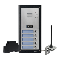
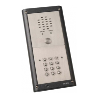
4G GSM AUDIO INTERCOM KIT
4000 Series GSM Audio Intercom with Proximity
66250754-4G-EN
V2.0 - 28/03/22
We recommend
This equipment is installed by a
Competent Electrician, Security or
Communications Engineer.
Technical Manual
ENG
GSM4K/4G
GSM4KCR/4G

Questions and Answers:

Videx GSM4K/4G Specifications

General IconGeneral
Operating Temperature-20°C to +55°C
GSM Frequency850/900/1800/1900MHz
Warranty2 years
TechnologyGSM/4G
NetworkGSM, 4G LTE
Relays2
Power Supply12V DC
HumidityUp to 95% non-condensing
Housing MaterialMetal
4G LTE BandsB1, B3, B7, B8, B20
Call FeaturesCall Forwarding

Summary

Declaration of Conformity

EU ROHS DECLARATION OF CONFORMITY

Declares conformity with EU RoHS directive standards.

RE Directive 2014/53/EU

Lists standards applied for radio equipment directive conformity.

WARNING!

Safety warning regarding RF exposure and product usage.

Introduction

MANUAL INTRODUCTION

Outlines the manual's purpose, recommendations, and contact information.

SYSTEM INTRODUCTION

Introduces the 4G GSM intercom system and its key features.

SIM CARD SELECTION

Specifies the type of SIM card required for the product.

NETWORK PROVIDER SELECTION

Guidance on selecting a suitable network provider for optimal system operation.

PRECAUTIONARY ADVICE

Important safety and installation advice before operating the system.

System Components and Available Versions

DESCRIPTION

Details the system components and the modular design of the intercom.

ART. 4810/4G GSM PRO INTERCOM AVAILABLE VERSIONS

Lists available configurations of the 4810/4G GSM PRO intercom module.

EXTENSION BUTTON MODULES

Describes compatible extension button modules for expanding call button capacity.

CONNECTING ART. 4042 .. 4045 IDC BUTTON MODULES

Explains how to connect IDC button modules using flat ribbon cables and jumper settings.

Button Offset Configuration

Details the feature for programming call button numbering and offset.

CONNECTING ART. 4842 .. 4845 BUTTON MODULES

Explains wiring standard button modules to the GSM intercom via matrix wiring.

BUTTON MATRIX WIRING

Illustrates the button matrix wiring diagram for connecting expansion buttons.

BUTTON MODULE WIRING NOTES

Provides notes on wiring additional button modules based on the GSM module's button count.

ART. 434 GSM ANTENNA & ART. 434 BLOCK ANTENNA

Describes the GSM antenna connections and types.

ANTENNA PARTS

Lists the individual parts included with the Art.434 GSM antenna kit.

IMPORTANT NOTE: AN ANTENNA MUST ALWAYS BE FITTED...

Critical note on antenna installation and cable routing to avoid interference.

ANTENNA CHARACTERISTICS

Details the technical specifications for the Art.434 GSM and Block antennas.

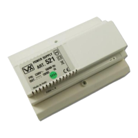
12VDC 2A POWER SUPPLY (HDR-15-12)

Describes the 12Vdc power supply unit and its specifications.

TERMINALS & ADJUSTMENT POTS

Lists terminals and adjustment pots on the power supply unit.

ART. 4903 CODELOCK

Introduces the Art.4903 codelock module and its features.

GSM INTERCOM AUDIO KITS

Lists various GSM intercom audio kits with their components for flush and surface mounting.

GSM4K 4G AUDIO KITS

Details the components for GSM4K-n/4G and GSM4K-nS/4G flush and surface kits.

GSM4KCR 4G AUDIO KITS

Details the components for GSM4KCR-n/4G and GSM4KCR-nS/4G flush and surface kits.

Art. 4810/4G Technical Information

ART. 4810/4G GSM MODULE

Provides a diagram and overview of the 4810/4G GSM module.

LEGEND

Explains the labels and symbols used in the module diagram.

NAMEPLATE ILLUMINATION JUMPER JP2

Details the function and adjustment of the JP2 jumper for nameplate illumination.

TERMINAL CONNECTIONS

Lists and describes the terminal connections on the GSM module.

terminals continued...

Continues the description of terminal connections and their functions.

CALL PROGRESS LED'S

Explains the meaning of the call progress LEDs on the GSM module.

TECHNICAL SPECIFICATION

Lists the key technical specifications of the Art.4810/4G GSM module.

Art. 4903 Technical Information

ART. 4903 CODELOCK MODULE

Introduces the codelock module with a diagram and description.

LEGEND

Explains the labels and symbols used in the codelock module diagram.

RS485 BUS TERMINATION JUMPER (JP1)

Details the function and settings of the RS485 bus termination jumper.

RELAY BUILT-IN BACK EMF PROTECTION (JP2 AND JP3)

Explains the back EMF protection jumpers for the relays.

BACK LIGHT ADJUSTMENT JUMPER (JPL)

Describes the JPL jumper for adjusting backlight brightness and modes.

PROGRAMMING MODE 1 (DEFAULT MODE, JPL = A)

Steps to set the codelock to programming mode 1.

PROGRAMMING MODE 2

Steps to set the codelock to programming mode 2.

BACK LIGHT AND BUTTON OPERATION

Explains how backlight behavior changes based on programming mode.

SETTING UP THE UNIT ID OF THE KEYPAD (ID 1-8)

Procedure for setting the unit ID for the codelock keypad.

PROGRAMMING AS A STANDALONE KEYPAD

Details how to program the codelock as a standalone unit.

PROGRAMMING GUIDE

Step-by-step guide for programming the codelock via keypad.

PROGRAMMING NOTES

Notes related to the programming process.

RESETTING THE CODELOCK BACK TO FACTORY DEFAULTS

Instructions to reset the codelock to factory default settings.

PROGRAMMING WHEN INTEGRATED WITH THE GSM PRO (ART.4810) MODULE VIA THE RS485 BUS CONNECTIONS

How to program the codelock when connected to the GSM module via RS485.

RS485 BUS CONNECTION AND WHEN TO FIT A 1200 RESISTOR

Details on RS485 bus connection and the use of termination resistors.

TERMINAL CONNECTIONS

Lists and describes the terminal connections for the Art.4903.

TECHNICAL SPECIFICATION

Technical specifications for the Art.4903 codelock.

Art. 4850R Technical Information

ART. 4850R PROXIMITY READER MODULE

Introduces the Art.4850R proximity reader with diagram and description.

LEGEND

Explains the labels and symbols used in the reader diagram.

RS485 BUS TERMINATION JUMPER

Details the function and settings of the RS485 bus termination jumper on the reader.

PROGRAMMING THE RELAY TIME (00, 01-99)

Instructions for programming the relay time for the Art.4850R.

SETTING THE UNIT ID (1 - 8)

Instructions for setting the unit ID for the Art.4850R reader.

TECHNICAL SPECIFICATION

Technical specifications for the Art.4850R proximity reader.

Wiring Diagrams

GSM4K/4G CONNECTIONS

Wiring diagram for GSM4K/4G series audio kits.

GSM4KCR/4G CONNECTIONS

Wiring diagrams for GSM4KCR/4G kits with Art.4903.

CONNECTING TO A GATE CONTROLLER

Diagrams showing how to connect the system to a gate controller.

CONNECTING A PUSH TO EXIT BUTTON AND A BREAK GLASS UNIT

Wiring diagrams for push-to-exit buttons and break glass units.

Auxiliary Inputs/Outputs

AUXILIARY OUTPUT A01

Details the functionality and modes of the AO1 auxiliary output.

A01 = MODE 00, 'CALL ACTIVATED'

Configuration for AO1 output to activate during a call.

A01 = MODE 01, 'USER ACTIVATED'

Configuration for AO1 output to activate via user input.

A01 = MODE 02, 'STATUS INDICATION'

Configuration for AO1 as a monitoring input for status.

A01 = MODE 03, 'DIVERT CALLS TO MASTER NUMBER'

Configuration for AO1 to divert calls to a master number.

A01 = MODE 04, 'CALL ACTIVATED (TIMED)'

Configuration for AO1 output to activate for a timed duration during a call.

A01 = MODE 05, 'ENABLE/DISABLE DIAL TO OPEN NUMBERS'

Configuration for AO1 to enable/disable dial-to-open numbers.

AUXILIARY OUTPUT AO2

Details the functionality and triggering methods for the AO2 auxiliary output.

AUXILIARY INPUT 2

Explains how auxiliary input 2 functions, sending SMS messages.

USB & RS485 Connection to a PC

CONNECTIONS TO A PC

Overview of PC connection methods for programming and monitoring.

OPTION 1: USB CONNECTION

Steps for connecting the GSM module to a PC via USB for programming.

OPTION 2: RS485 CONNECTION

Steps for connecting the GSM module to a PC via RS485 for programming and monitoring.

RS485 Network Connection

ART. 4903 NETWORK CONNECTION USING RS485

How to connect the Art.4903 codelock via RS485 for expanded features.

ART. 4850R NETWORK CONNECTION USING RS485

How to connect the Art.4850R reader via RS485 for expansion.

ART. 2813 NETWORK CONNECTION USING RS485

How to connect the Art.2813 remote relay via RS485.

SECURED BY DESIGN CONFIGURATION

Configuration options for secured access control networks.

SECURED BY DESIGN CONFIGURATION

Diagrams illustrating secured by design configurations with multiple devices.

EXTERNAL UNSECURED AREA

Diagram showing an unsecured area configuration.

NETWORK ACCESS CONTROL CONFIGURATION

Diagram showing network access control configuration.

General Directions for Installation

CABLE SIZE GUIDE

Guide for selecting appropriate cable sizes for power supply and lock release connections.

POWER SUPPLY AND LOCK RELEASE CONNECTIONS

Table showing cable connections for power and lock releases based on distance.

RS485 CONNECTIONS

Information on RS485 cable types, distances, and termination.

GENERAL INSTALLATION NOTES

General guidelines and safety precautions for installation.

LOCK RELEASE WIRING AND BACK EMF PROTECTION

Wiring and protection for electric lock releases.

CONNECTION TO MAINS, SAFETY AND GUIDANCE NOTES

Critical notes on mains connection, safety, and installation recommendations.

MAINS CONNECTION

Recommendations for mains connection through a circuit breaker and fuse spur.

POWER SUPPLY INSTALLATION

Steps for installing the HDR-15-12 power supply unit.

PANEL CARE

Guidelines for cleaning and maintaining the intercom panel fascia.

Fitting the SIM & Connecting Power

FITTING THE SIM CARD AND CONNECTING THE POWER TO THE GSM INTERCOM

Step-by-step guide for installing the SIM card and connecting power.

FITTING AND REMOVING THE SIM

Detailed instructions for inserting and removing the nano SIM card.

POWER UP INITIALISATION SEQUENCE

Describes the sequence of events during the GSM module's initial power-up.

Reset Procedure

RESETTING THE GSM MODULE TO FACTORY DEFAULTS

Explains the two hard-wired reset options for the GSM module.

RESETTING THE MASTER CODE TO 1111 (4x1)

Procedure to reset only the master code.

FULL SYSTEM RESET

Procedure to perform a full system reset, clearing all data.

4000 Series Back Box Installation

EXAMPLE: INSTALLING A 4000 SERIES FOUR MODULE BACK BOX

Illustrates the installation of a four-module back box.

INSTALLING A SURFACE MOUNT DOOR STATION

Step-by-step guide for installing a surface mount door station.

INSTALLING A FLUSH MOUNTING DOOR STATION

Step-by-step guide for installing a flush mount door station.

HOW TO REMOVE THE CARD NAME HOLDER

Instructions for removing and replacing the card name holder.

Programming the GSM Intercom

PROGRAMMING THE GSM INTERCOM

Overview of programming methods: SMS, PC software, and mobile apps.

PROGRAMMING BY TEXT MESSAGE

Explains how to program the intercom using SMS text messages.

4 DIGIT CODE

Information about the 4-digit code used for programming access.

3 DIGIT FUNCTION CODE

Explanation of the 3-digit function codes used in SMS commands.

Store a primary telephone no.

SMS command to store primary telephone numbers.

Store divert 1 telephone no.

SMS command to store the first divert telephone number.

Store divert 2 telephone no.

SMS command to store the second divert telephone number.

Store divert 3 telephone no.

SMS command to store the third divert telephone number.

Store an access code with an access level...

SMS commands for storing access codes with access levels and relay setup.

Store a temporary access code...

SMS commands for storing temporary access codes.

Find an access code

SMS command to find an access code's location.

Delete an access code without knowing its location

SMS command to delete an access code by its value.

STORING THE CALL BUTTON TELEPHONE NUMBERS (STN, STD, STE AND STF)

SMS commands for storing telephone numbers for call buttons.

STORING THE PRIMARY AND DIVERT NUMBERS IN A SINGLE TEXT MESSAGE (USING STN)

Method to store multiple telephone numbers in a single SMS.

STORING A DIAL TO OPEN NUMBER (STR)

SMS commands to store and manage Dial to Open numbers.

DELETE A DIAL TO OPEN NUMBER WITHOUT KNOWING IT'S LOCATION (DET)

SMS command to delete a Dial to Open number by its value.

SET CALL TIME (SPT)

SMS commands to set and check the call duration time.

SET RELAY TIME (RLT)

SMS commands to set and query the relay activation time.

SET AUXILIARY OUTPUT AO1 TIME (A1T, FOR A1M = 01 ONLY)

SMS commands to set the AO1 output time when in user-activated mode.

SET AUXILIARY OUTPUT A01 MODE (A1M, MODES 00 -05)

SMS commands to set the operating mode for the AO1 auxiliary output.

Divert Calls to Master Number: nn = 03

Setting AO1 mode 03 for call diversion.

Call Activate (Timed): nn = 04

Setting AO1 mode 04 for timed call activation.

Enable/Disable "Dial to Open": nn = 05

Setting AO1 mode 05 to control Dial to Open feature.

SET AUXILIARY OUTPUT AO2 TIME (A2T)

SMS commands to set the AO2 output time.

DIVERT TIME (DIT)

SMS commands to set and query the call divert time.

CHECK SIGNAL STRENGTH (SIG)

SMS command to check the GSM signal strength.

CHECK SOFTWARE VERSION (VER)

SMS command to check the GSM intercom software version.

FORCED DIAL/DIAL A NUMBER (DLE)

SMS command to dial a number for specific SIM card configurations.

STORE SMS AUXILIARY MESSAGE (SMS, WHEN AUXILIARY INPUT 2 IS TRIGGERED)

SMS command to customize the message sent when Auxiliary Input 2 is triggered.

CHANGE THE FOUR DIGIT CODE (CDE)

SMS command to change the 4-digit programming code.

TRIGGER THE RELAY (RLY)

SMS command to trigger the GSM relay.

TRIGGER AUXILIARY OUTPUT AO1 (A10)

SMS command to trigger the AO1 auxiliary output.

TRIGGER AUXILIARY OUTPUT AO2 (A20)

SMS command to trigger the AO2 auxiliary output.

STORE BALANCE CHECK DIAL STRING (SDL)

SMS command to store the dial string for checking SIM card balance.

CHECK CREDIT BALANCE (BAL)

SMS command to check the current balance of the SIM card.

STORE THE MASTER TELEPHONE NUMBER (STM)

SMS command to store the master telephone number for alerts.

LATCH THE RELAY (RLA)

SMS command to latch the GSM intercom relay.

UNLATCH THE RELAY (RUL)

SMS command to unlatch the GSM intercom relay.

LATCH AUXILIARY OUTPUT AO1 (A1L)

SMS command to latch the AO1 auxiliary output.

UNLATCH AUXILIARY OUTPUT AO1 (A1U)

SMS command to unlatch the AO1 auxiliary output.

LATCH AUXILIARY OUTPUT AO2 (A2L)

SMS command to latch the AO2 auxiliary output.

UNLATCH AUXILIARY OUTPUT AO2 (A2U)

SMS command to unlatch the AO2 auxiliary output.

STORE TIMEBAND FOR CALLS TO BE ACTIVE FOR (TBA)

SMS commands to set timebands for call availability.

USING ACCESS LEVELS WITH DIAL TO OPEN NUMBERS (STR)

Assigning access levels to Dial to Open numbers via STR command.

CHECK/SET DATE & TIME (CLK)

SMS commands to check and set the intercom's date and time.

CHECK INPUT STATUS (CHK)

SMS command to check the status of auxiliary output AO1.

SILENT DIALLING MODE (AUE)

SMS commands to enable/disable silent dialling.

SEND DTMF TONE AFTER CALL ANSWERED FOR CALL BUTTON 1(DTP, DTD AND DTT)

SMS commands to set DTMF tones and delays for call buttons.

ENABLE THE DIAL '0' ON ANSWER FUNCTION (EDZ)

SMS commands to enable/disable the dial '0' on answer function.

ENABLE THE # (HASH) FUNCTION (ED#)

SMS commands to enable/disable the '#' function for user commands.

ENABLE PROXIMITY READER (EPR)

SMS commands to enable or disable the proximity reader.

PROXIMITY NUMBER OF BYTES TO CHECK (PBY, 02, 03 & 04)

SMS commands to set the number of bytes the reader checks for fobs/cards.

FIND A FOB OR CARD (FDF)

SMS command to find a fob/card's location.

DELETE A FOB OR CARD WITHOUT KNOWING ITS LOCATION (DEF)

SMS command to delete a fob/card without knowing its location.

STORE AN ACCESS CODE TO A KNOWN LOCATION (000 - 399) OR STORE IN THE NEXT AVAILABLE LOCATION (PIN)

SMS commands to store access codes in known or next available locations.

STORE AN ACCESS CODE WITH AN ACCESS LEVEL (PIN) INCLUDING RELAY SETUP

Storing access codes with access levels and relay setup.

STORE A TEMPORARY ACCESS CODE IN THE NEXT AVAILABLE LOCATION (TMP)

SMS commands to store temporary access codes.

FIND AN ACCESS CODE (FDC)

SMS command to find an access code's memory location.

DELETE AN ACCESS CODE WITHOUT KNOWING ITS LOCATION (DEC)

SMS command to delete an access code by its value.

DELETE ALL TEMPORARY ACCESS CODES (DEP)

SMS command to delete all temporary access codes.

CLEAR ALL FREE ACCESS TIMEBANDS (FRD)

SMS command to clear all free access timebands.

DISABLE OR ENABLE SPEECH BOARD (SBM)

SMS commands to disable or enable the speech board.

SET SPEECH BOARD VOLUME (SBV)

SMS commands to adjust the speech board volume.

FIND A TELEPHONE NUMBER (FDT)

SMS command to find Dial to Open number locations.

END ON LAST DIVERT (EOD)

SMS commands to enable/disable the end on last divert feature.

DOOR OR GATE (GAT)

SMS commands to configure speech annunciation for door/gate status.

SHUTDOWN AND RESTART (RBT)

SMS command to remotely shut down and restart the GSM module.

SIMULATE A BUTTON PRESS VIA SMS MESSAGE FOR BUTTONS 01-50 (BUT)

SMS command to simulate button presses for testing.

ENABLE EXTENDED OUTPUT TIMES (EXO)

SMS commands to enable extended output times for relays and auxiliary outputs.

OBTAIN THE GSM'S IMEI NUMBER (IME)

SMS command to obtain the GSM module's IMEI number.

UNLATCH PREVENTION FEATURE (LLA)

SMS commands to enable/disable the unlatch prevention feature.

NETWORK CONNECTION INDICATION (CON)

SMS command to check the GSM module's network connection type.

SETUP THE GSM INTERCOM FOR DATA COMMUNICATION (APN)

Steps to set up the GSM intercom for data communication using APN details.

STORE A USERNAME & PASSWORD FOR EACH GSM MODULE FOR ONLINE EVENTS (PAS)

SMS commands to store username and password for online event monitoring.

ENABLE ONLINE EVENTS FOR THE GSM MODULE (ENE)

SMS commands to enable or disable online event reporting.

SETUP PORT FORWARDING FOR CONNECTION TO A SERVER (SER)

SMS command to configure port forwarding for server connection.

SOURCE OF TIME/DATE UPDATES (NTZ)

Explanation of time/date update sources and modes.

UTC TIME ZONE FOR COUNTRIES AHEAD OF UTC (TZ+)

SMS commands to set the time zone ahead of UTC.

UTC TIME ZONE FOR COUNTRIES BEHIND UTC (TZ-)

SMS commands to set the time zone behind UTC.

DAYLIGHT SAVINGS TIME ADJUSTMENT (DST)

SMS commands to enable/disable daylight savings time adjustment.

SEND GLOBAL ANNOUNCEMENT FEATURE (SGA)

SMS command to send a global announcement message.

BUTTON OFFSET CONFIGURATION (BOF)

SMS commands to configure button offset for call button numbering.

BUTTON OFFSET CONFIGURATION (BOF)

Example and diagrams for configuring button offset.

ACTIVATE REMOTE RELAY OUTPUT (RLN)

SMS commands to activate remote relay outputs via Art.2813.

The GSM Mobile Apps

VIDEX SMS ACCESS, SMS WIZARD & SMS WIZARD PRO

Overview of mobile apps for programming and managing the GSM intercom.

WHERE TO DOWNLOAD THE MOBILE APPS AND GETTING STARTED

Information on downloading and initial setup for the mobile apps.

System Operation

MAKING A CALL AND CANCELLING A CALL FROM THE GSM INTERCOM TO THE PHONE

Steps for making and cancelling calls from the intercom to a phone.

ANSWERING AND ENDING A CALL FROM THE GSM INTERCOM

How to answer and end calls received on the GSM intercom.

DIVERTED CALL

Explanation of how diverted calls are handled.

RELEASING THE DOOR/GATE FROM THE PHONE AFTER A CALL FROM THE GSM INTERCOM (INC. LATCH/UNLATCH)

How to release or latch the door/gate from the phone after a call.

RELEASING THE DOOR/GATE USING THE ONBOARD PROXIMITY READER

Operation of the onboard proximity reader for access control.

ACCESS GRANTED (ONBOARD READER)

Behavior when a programmed fob/card is presented to the onboard reader.

ACCESS DENIED (ONBOARD READER)

Behavior when an unrecognised fob/card is presented to the onboard reader.

ACTIVATING THE ART. 4850R EXPANSION READER'S ONBOARD RELAY

How to activate the relay on the Art.4850R expansion reader.

ACCESS GRANTED (ART.4850R)

Operation of the Art.4850R reader when access is granted.

ACCESS DENIED (ART.4850R)

Operation of the Art.4850R reader when access is denied.

ACTIVATING THE ART. 4903 CODELOCK'S RELAYS

How to activate the Art.4903 codelock's relays.

STANDALONE OPERATION I.E. NOT CONNECTED VIA RS485

Operation of the codelock when used standalone.

CORRECT CODE ENTERED (ACCESS GRANTED - STANDALONE MODE)

Behavior when a correct code is entered in standalone mode.

INCORRECT CODE ENTERED (ACCESS DENIED - STANDALONE MODE)

Behavior when an incorrect code is entered in standalone mode.

OPERATION WHEN CONNECTED TO THE GSM INTERCOM VIA RS485

Operation of the Art.4903 codelock when connected via RS485.

CORRECT CODE ENTERED (ACCESS GRANTED - RS485 CONNECTION)

Behavior when a correct code is entered via RS485.

INCORRECT CODE ENTERED (ACCESS DENIED - RS485 CONNECTION)

Behavior when an incorrect code is entered via RS485.

User Commands

USER COMMAND TABLES

Tables detailing user commands for calls and SMS messages.

FUNCTION

Lists functions and their corresponding commands or key presses.

Additional User Information

UNDERSTANDING THE SIGNAL STRENGTH (SIG) AND BIT ERROR RATE (BER)

Explains how to interpret signal strength and bit error rate messages.

DIALLING INTO THE GSM INTERCOM FROM ANOTHER TELEPHONE

Describes the outcomes of dialling into the GSM intercom.

UNDERSTANDING THE BEEPS

Explains the meaning of various beeps from the GSM intercom.

PROXIMITY READER (ONBOARD READER AND/OR ART.4850R EXPANSION READER)

Explains beep codes related to proximity reader operation and troubleshooting.

ART.4903 CODELOCK (WHEN CONNECTED VIA RS485)

Explains beep codes related to the Art.4903 codelock operation via RS485.

User Management

RECORD SHEET

Recommendation to keep a record sheet for programming and settings.

USING THE GSMSK PC SOFTWARE TO MANAGE USER INFORMATION AND DOWNLOAD STORED EVENTS

How to use GSMSK PC software for managing data and downloading events.

MANAGING GSM EVENTS REMOTELY

Steps to set up remote event monitoring via web application.

Troubleshooting

SYSTEM CHECKS AND TESTING

Table diagnosing potential issues and providing solutions.

Interference on the speech.

Troubleshooting steps for speech interference.

The intercom panel repeatedly beeps twice...

Troubleshooting steps for panel beeping and illumination issues.

No telephone number programmed...

Troubleshooting steps for when the intercom doesn't respond to SMS.

Unable to open the gate/door from the telephone during a call (DTMF tones not being recognised)

Troubleshooting steps when DTMF tones for gate/door release are not recognised.

General Information

FIRMWARE REVISION

List of firmware versions and their revisions.

FURTHER READING

List of additional technical manuals and application notes for further information.

DISPOSAL

ENG DISPOSAL

Information on the disposal of electrical and electronic equipment (WEEE).

Related product manuals