Do you have a question about the Videx 940ST and is the answer not in the manual?
Overview of the manual's purpose and installation guidance.
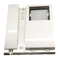
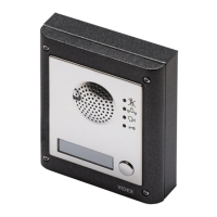
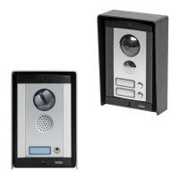
System components, features, and optional extras for the Sentry 1 system.
How the Sentry 1 system functions during calls and access granting.
Key electrical and operational parameters of the Sentry 1 system.
Detailed breakdown of terminal connections on the Sentry 1 PCB.
Functionality and operation of the 4-way isolation PCB.
How the isolation PCB handles calls and triggers relays.
Electrical specifications for the 4-way isolation PCB.
Diode installation for suppressing back EMF on lock releases.
Recommended cable specifications and resistance limits for intercom systems.
Essential grounding and continuity checks for system safety.
Procedures for verifying system functionality after installation.
Wiring diagram for the busy lamp feature.
Wiring diagram for fail-safe lock release configuration.
Wiring diagram for integrating a fireman's switch.
Wiring diagram for connecting an extension speaker.
Wiring diagram for adding an extension strobe.
Wiring diagram for the push-to-exit function.
Diagnosing and fixing no speech from door panel or handset.
Troubleshooting handset bleeps, ringing, and calltone issues.
Resolving issues with lock release and immediate operation.
Diagnosing no button response and speech line hum.
Procedure for initiating a call to an apartment from the door panel.
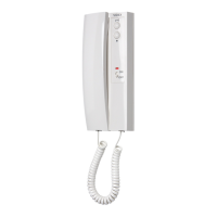
How to answer calls and grant access via the handset.
Instructions for exiting the building using the push-to-exit button.
How to use the nuisance switch to disable incoming calls.
| Power Supply | 12Vdc |
|---|---|
| Door Release | Yes |
| Privacy | Yes |
| Operating Voltage | 12Vdc |
| Housing Material | ABS Plastic |
| Button Material | Plastic |
| Audio Output | Internal Speaker |
| Audio Input | Electret Microphone |
| Mounting | Surface Mount |
| Compatibility | Videx 3000 Series |