66250754-4G-EN - V2.0 - 28/03/22
- 20 -
4000 Series GSM Audio Intercom - Technical Manual
4000 Series GSM Audio Intercom with Proximity
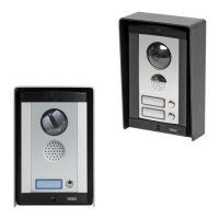
ART. 4850R PROXIMITY READER MODULE
103mm
120mm
Fig. 14
DESCRIPTION LEGEND
The Art.4850R proximity reader is an expansion reader that can be connected
to the Art.4810/4G GSM module via an RS485 bus connection. It allows the GSM
intercom to have up to 7 additional proximity access doors or can be used with
a combination of proximity and coded access using the Art.4903 keypad (up to
a total of 8 devices with the GSM module’s onboard reader as device ID.1).
The front of the module has a tri-colour LED to indicate to the user the status of
the reader (amber = standby, green = access granted and red = access denied).
The reader is housed in a 4000 series module with a stainless steel or aluminium
surround front frame, see Fig.14.
When connected to the 4G GSM intercom with the RS485 bus connection it can
be programmed by sending SMS text messages (refer to notes programming
the GSM intercom on pages 37 - 66), using the GSMSK PC software or using the
Videx SMS Wizard or Videx SMS Wizard PRO GSM mobile apps.
Proximity reading area
Status indication LED
Current rmware version (FW X.X)
Programming indication LED's (yellow)
Tens and Units programming buttons
Power input terminals
PTE input & relay (C/NC/NO) terminals
RS485 bus termination jumper
RS485 bus terminals
Store and Delete programming buttons
Store LED (green) and Delete LED (red)
It has a single onboard relay with common (C), normally open (NO) and normally closed (NC) connections and a switched 0V push
to exit input (PTE) to enable the activation of the relay. The relay operating time can be set for 01 - 99 seconds or 00 for latching
and can be programmed by using a combination of the tens, units and store buttons on the back of the module (also refer to
programming the relay time on page 21). Presenting a programmed fob will activate the relay for the programmed relay time.
The unit ID (1 - 8) can be set by using a combination of the units, store and delete buttons on the back of the module (also refer to
setting the unit ID on page 21).
IMPORTANT NOTE: The Art.4850R reader can only be used as an expansion reader for the GSM intercom, therefore programming
can only be carried out (when connected by RS485) by sending SMS text messages to the GSM module, by using the GSMSK
PC software (software version 4.1.0.35 or later) or by using the GSM modile apps. The only manual programming that can be
performed on the module is the unit ID setup and relay time. All proximity fob data is actually stored in the GSM module’s memory
and not the proximity reader. Compatible key fobs: 955/T, 955/B, 955/R, 955/G and/or 955/Y ; compatible proximity cards: 955/C.
IMPORTANT NOTE: MIFARE PROXIMITY FOBS/CARDS CANNOT BE USED WITH THIS READER.
RS485 BUS TERMINATION JUMPER
The jumper on the rear of the proximity reader sets the RS485 bus termination when
connected to the GSM module or other RS485 devices, see Fig.15.
By default the jumper is set to the closed position (lower two pins).
When more than one RS485 device is connected to the reader in line and on the RS485
bus the jumper can be set to OPEN (upper two pins).
Fig. 15
Art. 4850R Technical Information

 Loading...