Installation Instructions
22 of 38
IM-PP 724607 1218 ProPress
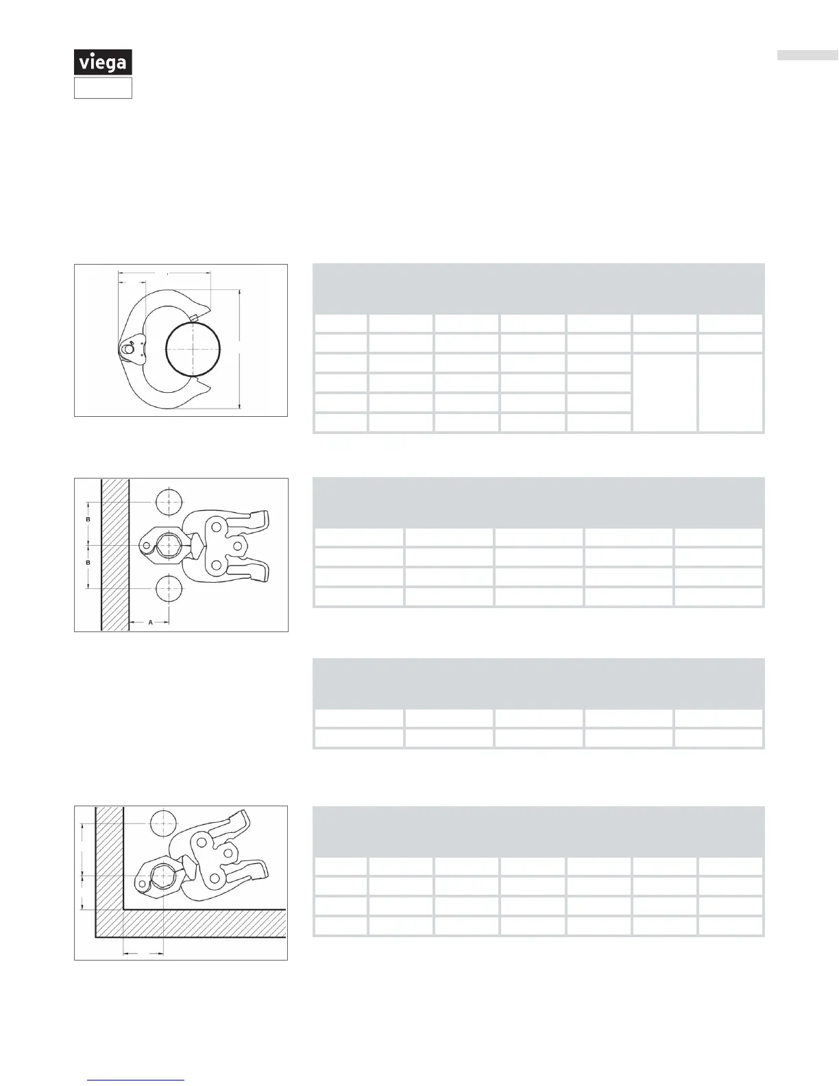
4.3.4 ProPress Rings Clearance Requirements
Ensure that the space required for system pressing tools is available
if Viega ProPress ttings will be installed immediately upstream or
downstream from ceiling penetrations.
Tube
Diameter
(inches)
A
minimum
(inches)
A
minimum
(mm)
B
minimum
(inches)
B
minimum
(mm)
C
minimum
(inches)
C
minimum
(mm)
½ 2¼ 57 2⅛ 54 1
1
/
16
27
¾ 2
11
/
16
68 2⅞ 73 1⅛ 28
1 2
15
/
16
75 3
5
/
16
84
1
3
/
16
30
1¼ 3
5
/
16
84 3⅞ 99
1½ 3
11
/
16
94 4
5
/
16
110
2" 4
7
/
16
113 5
7
/
16
139
Table 8: ProPress rings dimensions
Tube
Diameter
(inches)
A
minimum
(inches)
A
minimum (mm)
B
minimum
(inches)
B
minimum (mm)
½ 1⅝ 41 2
3
/
16
71
¾ 1¾ 45 2
3
/
16
55
1 2 51 1⅝ 42
1¼ 2
3
/
16
55 2
15
/
16
75
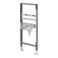
Table 9: ProPress rings with V1 Actuator clearance requirements
Tube
Diameter
(inches)
A
minimum
(inches)
A
minimum (mm)
B
minimum
(inches)
B
minimum (mm)
1½ 2⅜ 60 3
5
/
16
85
2 2
9
/
16
65 4⅛ 105
Table 10: ProPress rings with V2 Actuator clearance requirements
Tube
Diameter
(inches)
A
minimum
(inches)
A
minimum
(mm)
B
minimum
(inches)
B
minimum
(mm)
C
minimum
(inches)
C
minimum
(mm)
½ 1⅝ 41 3
9
/
16
90 2
5
/
16
59
¾ 1¾ 45 3⅝ 92 2⅛ 55
1 2 51 3
13
/
16
97 2
3
/
16
56
1¼ 2
3
/
16
55 3¾ 92 2⅛ 55
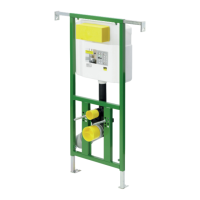
Table 11: ProPress rings with V1 Actuator clearance requirements between tube, wall,
and oor
C
B
A
A
B
C