Installation Instructions
31 of 38
IM-PP 724607 1218 ProPress
Tube Diameter (inches) Insertion Depth (inches)
2½ 1
11
/
16
3 1
15
/
16
4 2⅜
Table 22: Minimum insertion depths ProPress XL-C
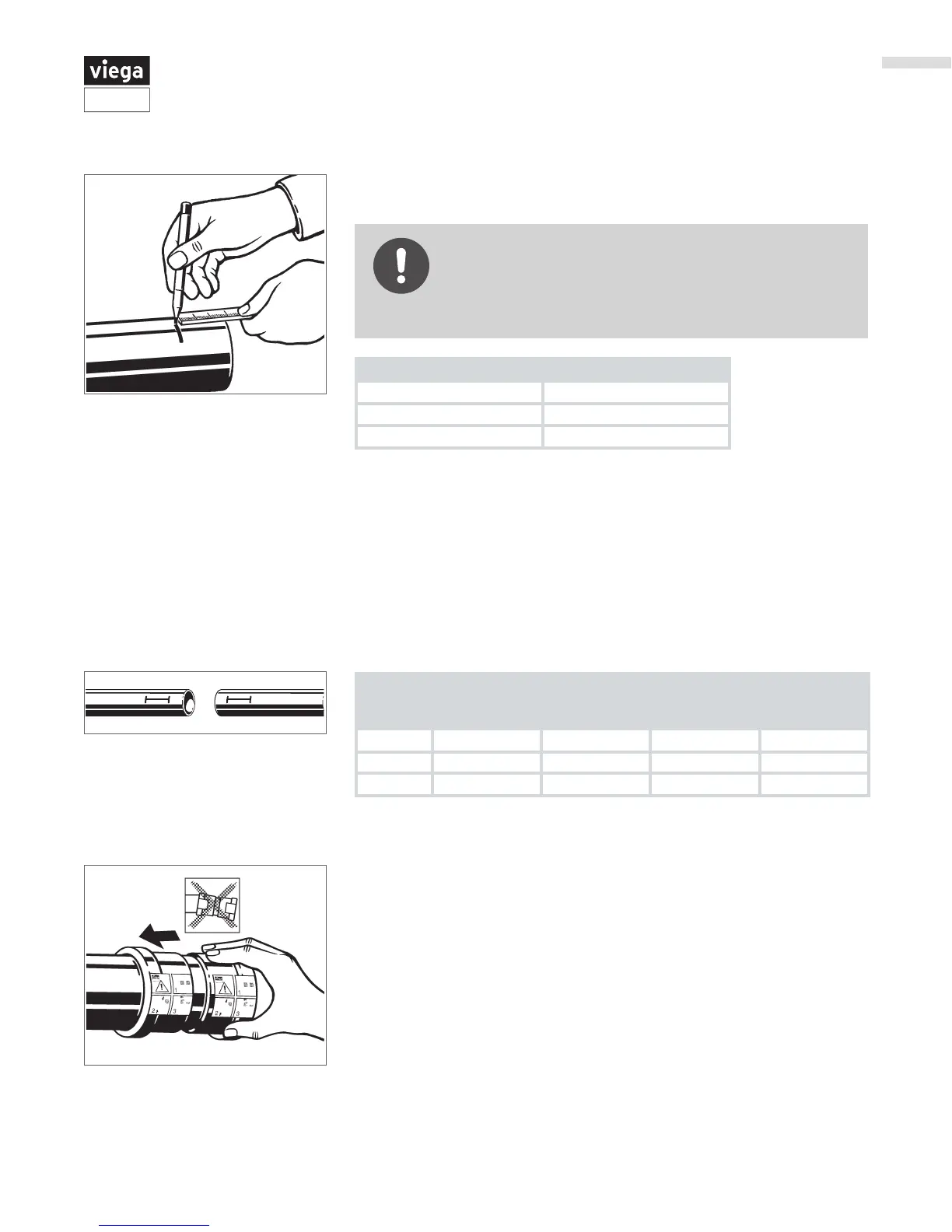
▶ Measure insertion depth (see table below).
▶ Mark the proper insertion depth on the outside of the tube.
Improper insertion depth
Improper insertion depth may result in an improper seal.
■ Be sure to mark the correct insertion depth on the tube
before pressing the tting.
Tube
Diameter
(inches)
Minimum
Insertion
Depth (inches)
Minimum
Insertion
Depth (mm)
Maximum
Insertion
Depth (inches)
Maximum
Insertion
Depth (mm)
2½ 1
11
/
16
43 2⅝ 67
3 1
15
/
16
50 2
15
/
16
75
4 2⅜ 60 3
7
/
16
87
Table 23: Insertion depths for ProPress XL-C non-stop couplings
Non-stop couplings and extended non-stop couplings are often used to
conduct repairs. Without a stop, these couplings can slide completely
onto a tube and allow a connection to be made in tighter spaces. Unlike
ttings with an integrated stop that have a minimum insertion depth,
non-stop couplings have minimum and maximum allowable insertion
depths. Both the minimum and the maximum insertion depths must be
marked and a line connecting the two marks. Drawing a line between the
minimum and maximum insertion marks distinguishes a good connection
on a non-stop tting from a bad connection on a tting with a stop.
▶ While turning slightly, slide tting onto the tube to marked insertion
depth.
Note: End of tube must contact stop.