8
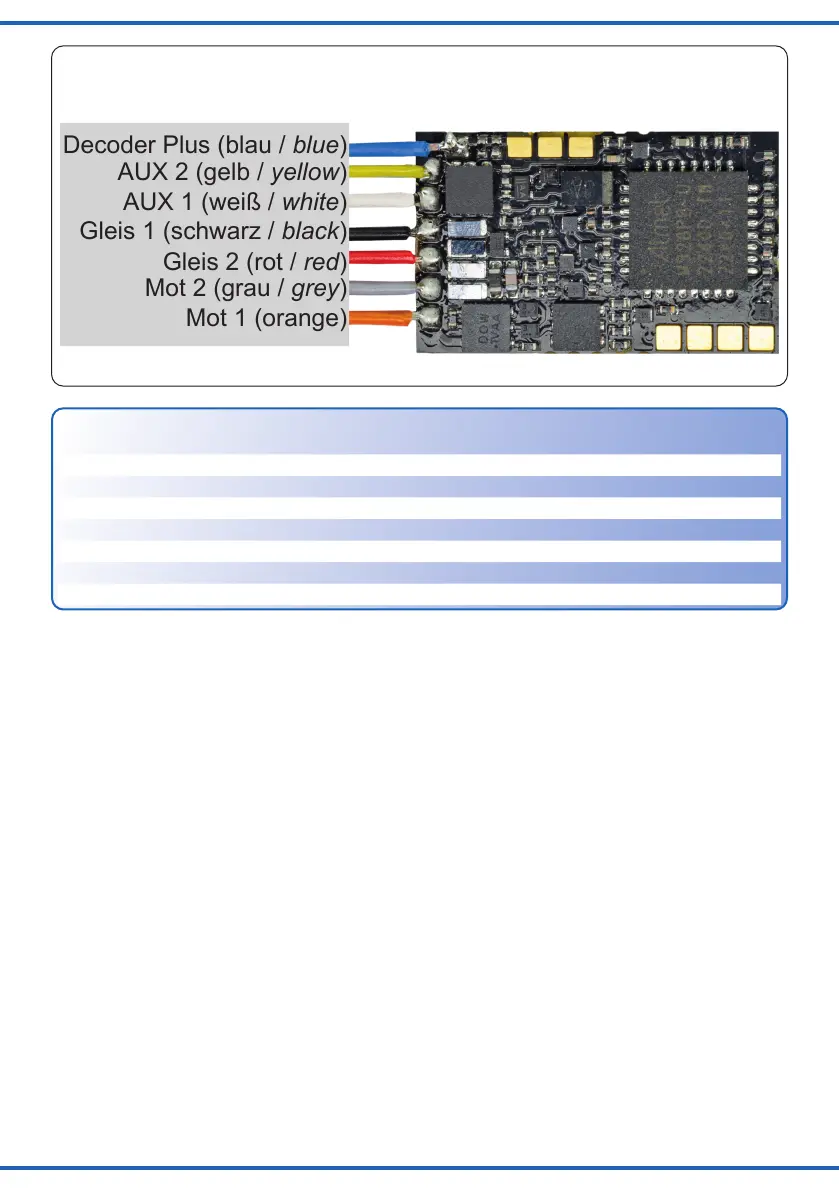
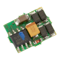
Mot 2 (grau / grey)
Mot 1 (orange)
AUX 1 (weiß / white)
Gleis 1 (schwarz / black)
Gleis 2 (rot / red)
AUX 2 (gelb / yellow)
Decoder Plus (blau / blue)
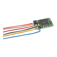
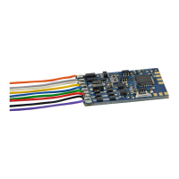
Fig. 3
Abb. 3
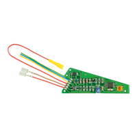
3.1 Decoder 5297: Einbau in Loks
mit NEM 651-Schnittstelle
- Öffnen Sie die Lok und entfernen Sie den Brü-
ckenstecker aus der Schnittstellenbuchse der
Lok.
- Stecken Sie den NEM 651-Stecker des Decoders
in die Schnittstellenbuchse der Lok.
Kleben Sie in der Nähe befindliche Metallteile mit
Isolierbandab,damitsienichtdenSteckerberüh-
ren können.
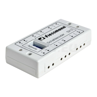
3.2 Decoder 5296: Einbau in Loks ohne
NEM 651-Schnittstelle
ZumEinbauinLoksohneSchnittstellenbuchsever-
wenden Sie bitte den Decoder mit Anschlussdräh-
ten(Art.5296).BeachtenSieunbedingtdieBele-
gungderAnschlüsse(Tabelleoben)unddieAbb.3.
- TrennenSiedieVerbindungendesMotorszu
den Stromabnehmern Radkontakte bzw. bei Loks
mitelektronischemUmschalterdieVerbindungen
des Umschalters zum Motor und zu dem Schlei-
fer bzw. zu den Radkontakten. Der Umschalter
wird nicht mehr benötigt und sollte entfernt wer-
den.
3.1 Decoder 5297: Installation in
locomotives with NEM 651 surface
- Remove the housing and also the bridge plug
from the interface socket.
- Insert the NEM 651 plug into the socket.
Insulate all metal parts close to the decoder so that
they cannot touch the plug..
3.2 Decoder 5296: Installation in
locomotives without NEM 651 surface
Please use the decoder item 5296 with wire har-
ness but without plug for installation in locomotives
without NEM socket. Observe the contact configu-
ration as per (above table) and fig 3.
- Disconnect the motor from the wheel pick-ups
or the change-of-direction relay respectively the
wires from the electronic relay to the motor and
to the centre pick-up or wheel contacts. The re-
lay is no longer needed and should be removed.
Anschluss
Connector
Farbe Funktion
Colour Function
Decoder Plus blau DecoderVersorgung(300mA) blue Decoder supply (300 mA)
AUX 2 gelb Schlusslicht(max.300mA) yellow Rear light (max. 300 mA)
AUX 1 weiß Spitzenlicht(max.300mA) white Forward headlight (max. 300 mA)
Gleis 1 schwarz Radstromkontakt rechts black Right track connection
Gleis 2 rot Radstromkontakt links red Left track connection
Mot 2 grau Motorausgang(bis0,5A) grey Motor (max. 0.5 A)
Mot 1 orange Motorausgang(bis0,5A) orange Motor (max. 0.5 A)
Anschlussschema / Wiring connections