9
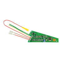
- LötenSiedievondenRadkontaktenkommenden
AnschlüsseandenKabeln„Gleis1“und„Gleis2“
an.
- LötenSiedanndievomMotorkommendenAn-
schlüsseandenPunkten„Mot1“und„Mot2“an.
Sollte die Fahrtrichtung der Lok im Analogbetrieb
nicht mit der am Trafo eingestellten Fahrtrich-
tung übereinstimmen, müssen Sie die Anschlüs-
se„Gleis1“und„Gleis2“austauschen.
Sollte die Fahrtrichtung im Digitalbetrieb nicht
stimmen,sovertauschenSiedieAnschlüsse
„Mot1“und„Mot2“.
Vorsicht:
Die Entstörmittel, die am Motor oder in der Zulei-
tung angebracht sind, dürfen nicht entfernt wer-
den! Motor und Entstörmittel bilden eine Einheit.
Wird nur ein Teil entfernt, kann es zu erheblichen
elektrischen Störungen kommen.
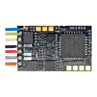
3.3 Decoder 5297: Einbau in Loks mit
Next18 Buchse
- Stecken Sie den 18-poligen Stecker in die Buch-
se auf der Systemplatine der Lok.
3.4 Anschluss von Verbrauchern an die
Funktions- bzw. Lichtausgänge
PrüfenSievordemAnschlussderBeleuchtungund
weiterer Zusatzgeräte an die Funktionsausgänge,
ob der Strom aller Funktionen zusammen unterhalb
desmaximalzulässigenWertesvon300mAliegt
und der Motorstrom 500 mA nicht dauerhaft über-
steigt.WerdenBeleuchtungenoderandereVer-
brauchermiteinemStromvonmehrals300mA
gleichzeitig an den Decoder angeschlossen oder
beträgt der Gesamtstrom aller angeschlossenen
VerbraucherunddesMotorsmehrals800mA,so
wird der Decoder thermisch überlastet und schal-
tet ab.
EntfernenSieeventuellvorhandeneDiodeninden
Zuleitungen zu den Lampen.
Wenn der Rückleiter des Zusatzgerätes bereits mit
Fahrzeugmasseverbundenist,istderAnschluss
damitfertiggestellt.AndernfallsschließenSieden
jeweiligen Rückleiter der Lampen und Zusatzgeräte
andenVersorgungsanschlussfüralleFunktionen
desDecoders„DecoderPlus“an.
3.5 Werkseitige Decodereinstellungen
Die werkseitigen Decodereinstellungen sehen
folgendenAnschlussvor:
- Beleuchtungvorne:AUX1
- Beleuchtung hinten: AUX2
- Rangiermodus schaltbar über F4
- Solder the wires coming from the wheel contacts
to the pads “Gleis 1” and “Gleis 2” (track 1 and
track 2).
- Next solder the wires from the motor to the points
“Mot1” and “Mot2”. Should the locomotive´s di-
rection in analogue mode not match the direction
of travel of your transformer you should swap the
wires on “Gleis 1” and “Gleis 2”.
If the direction of travel is not correct in digi-
tal mode simply swap the wires on “Mot1” and
“Mot2”.
Caution:
The interference suppression devices wired di-
rectly to the motor or the leads to the motor must
not be removed! Motor and interference suppres-
sion devices are one unit. If even one part is re-
moved, it may cause considerable electrical in-
terference!
3.3 Decoder 5297: Einbau in Loks mit
Next18 Buchse
- Stecken Sie den 18-poligen Stecker in die Bu-
chse auf der Systemplatine der Lok.
3.4 Connecting accessories to the
function resp. lighting outputs
Before connecting lighting and other accessories
to the function outputs check if the total current is
below the maximum permissible value of 300 mA
and the motor current is below 500 mA (continu-
ous). If you connect lighting or other accessories
with a total current higher than 300 mA simultane-
ously, or if the total current of the motor and the
accessories is higher than 800 mA the decoder will
be thermally overloaded and will switch itself off.
Please disconnect any diodes in the leads to the
lamps.
If the return wire of the lamp or the accessory is al-
ready connected to vehicle ground (common) wir-
ing is complete. If not, connect the second pole of
the lamp or the accessory to the common conduc-
tor ”decoder plus” of the decoder.
3.5 Factory default settings
The factory settings are as follows:
- Headlight: AUX1
- Rear light: AUX2
- Shunting mode F4