10
3.6 Anschluss von LEDs
Die Funktionsausgänge des Lokdecoders schalten
gegen Decodermasse. Daher müssen am Ausgang
derFunktionsausgängedieKathoden(„Minusan-
schluss“)derLEDsangeschlossenwerden.
Vorsicht:
Wenn Sie LEDs einsetzen, müssen Sie diese im-
merübereinenVorwiderstandbetreiben!DieVor-
widerstände sind je nach Strom und Bauform der
Leuchtdioden unterschiedlich. Ermitteln Sie die
richtigen Werte oder erfragen Sie sie beim Kauf.
Sie können mehrere LEDs an einen Ausgang pa-
rallelanschließen.DabeibenötigtjedeDiodeei-
neneigenenVorwiderstand.WennSiemehrere
LEDsaneinenAusganginReiheanschließen,
reichteinVorwiderstandaus.
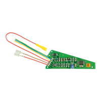
3.7 Anschluss eines SUSI-Moduls
DerDecoderhatvierLötpadsfürdenAnschluss
einesSUSI-Moduls.DieBelegungderAnschlüsse
entnehmen Sie bitte der Abb. 4.
3.8 Anschluss eines Stützkondensators
InFahrabschnittenmitschlechtemKontaktkanndie
StromversorgungdesDecodersimmerwiederkurz
unterbrochenwerden.ZwischendenPunkten„Elko-
“und„Elko+“könnenSieeinenStützkondensator(z.
B.100μF/25V)anlöten,derdieStromversorgung
verbesserts.Abb.4.
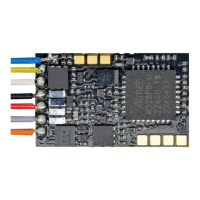
3.9 Befestigung des Lokdecoders
Nach Fertigstellung aller Anschlüsse sollten Sie den
Lokdecoder befestigen, sofern das Fahrzeug nicht
übereinengeeignetenEinbauraumverfügt.Dies
kann z. B. mit doppelseitigem Klebeband erfolgen.
4. Programmierung
BevorSiemitdemProgrammierendesLokde-
coders beginnen, muss der Motor an den Decoder
angeschlossen sein, da sonst keine Rückmeldung
zur(DCC-)Zentraleerfolgenkann.
Wenn Sie den Decoder mit einer Motorola-Zentrale
programmieren wollen, sollten Sie an die Ausgänge
AUX1undAUX2Beleuchtungenanschließen,da
die Lok den Wechsel in den Programmiermodus
und die Übernahme der Eingaben durch das Blin-
ken der Beleuchtung an diesen Ausgängen quittiert.
ImDCC-FormatkönnenSiedieseKonfigurations-
variablen(CVs)programmieren.Die„Hauptgleis-
programmierung“(POM)istebenfallsmöglich.Im
Motorola-Format werden die Einstellungen in so-
genannte Register programmiert, die Zählweise ist
mitderderCVsidentisch.
3.6 Connecting the LEDs
The return of the function outputs of the decoder
must be wired the decoder ground (“Vers.”). For
that reason you must connect the cathodes (-) of
the LEDs to the function outputs.
Caution:
LEDs must always be wired via serial resistor!
The resistor value depends on the type and cur-
rent draw of the LEDs. Determine the appropri-
ate value or enquire when purchasing the LEDs.
You can connect several LEDs in parallel to each
output. In this case every LED must have a serial
resistor of its own. If you connect several LEDs
to one output in series, only one serial resistor
is required.
3.7 Connecting SUSI modules
The decoder has four soldering pads for connect-
ing a SUSI module. The allocation of each pad is
shown in fig. 4.
3.8 Connecting a buffer capacitor
On tracks with poor contact the power supply to the
decoder may be momentarily interrupted. In order
to resolve this issue you may solder a buffer ca-
pacitor to the pads “Elko-“ and “Elko+” (e. g. 100μF
/25V). Also refer to fig. 4.
3.9 Installing the decoder
After having made all connections you should fix
the decoder in the locomotive. If there is no spe-
cific decoder compartment in the locomotive you
may simply use some double-sided adhesive tape.
4. Programming
Before starting the programming you should con-
nect the motor to the decoder in order to assure the
necessary feedback from the decoder to the (DCC)
command station.
Should you intend to program the decoder with a
Motorola central unit you should always connect
the lighting to the outputs AUX1 and AUX2. The
locomotive confirms the change into the program-
ming mode and the acceptance of programming
commands by flashing the lights.
In DCC format you can program the configuration
variables (CVs). This can also be done by “Pro-
gramming on the Main” (POM). In the Motorola for-
mat the settings are saved in so called registers.
The method of counting is the same as with the
CVs.