6
M
M
M
M
M
M
M
A
S
O
P R
V
W
B
C
D
E
F
G
H
K
LM
U
T
N
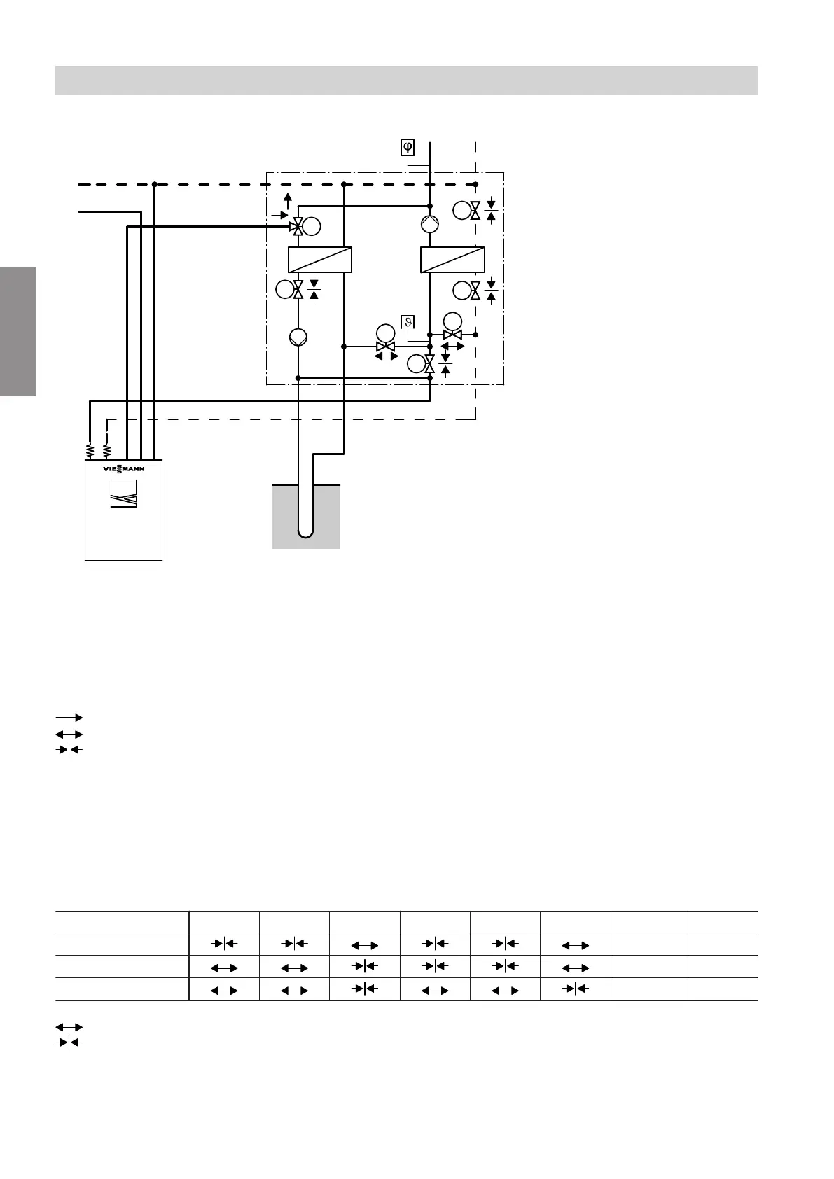
Fig.1
Note
■
Valve switching states without switching by the heat
pump.
■
Component layout inside the appliance: See
page 21.
Direction of flow, 3-way diverter valve
Valve open
Valve closed
A
2-way valve V1
B
2-way valve V2
C
2-way valve V3
D
2-way valve V7
E
2-way valve V5
F
2-way valve V6
G
3-way diverter valve V4
H
High efficiency circulation pump M2
K
High efficiency circulation pump M1
L
Plate heat exchanger 1
M
Plate heat exchanger 2
N
Frost stat
O
AC-Box
P
Contact humidistat 24 V– (accessories)
R
Flow, heating/cooling circuit or separate cooling
circuit
S
Return, heating/cooling circuit or separate cool-
ing circuit
T
Geothermal probe
U
Heat pump
V
DHW cylinder flow
W
DHW cylinder return
Switching states of the integral 2-way valves and circulation pumps
Active signal
V1
A
V2
B
V3
C
V5
E
V6
F
V7
D
M1
K
M2
H
None
0 0
NC signal
\ 0
AC signal
\ \
Valve open
Valve closed
\ ON
0 OFF
Preparing for installation
Hydraulic function diagram
5675 895 GB
Installation