Set-up
10
Mechanical Room
During the early stages of new home design, we recommend that proper
consideration be given to constructing a separate mechanical room dedicated to
gas- or oil-fired equipment including domestic hot water storage tanks.
The boiler must be located in a heated indoor space, near a floor drain, and as close
as possible to the v ertical chimney or vent.
Whenever possible, install boiler near an outside wall so that it is easy to duct fresh
air directly to the boiler area. In addition, do not use exhaust fans in the boiler room
and do not install the boiler in rooms with refrigeration equipment. This equipment
requires uncontaminated outside air for safe operation - do not install where
chemicals are stored or in a room with negative pres sure. See section entitled
“Combustion Air Supply” starting on page 12 for further details regarding the
above.
Locate boiler on f looring capable of supporting the weight of the boiler filled with
water. Pour a concrete pad if necessary. Ensure that the boiler location does not
interfere with the proper circulation of combustion and ventilation air within the
mechanical room.
The maximum room temperature of the mechanical room where the boiler is located
must not exceed 104°F/40°C.
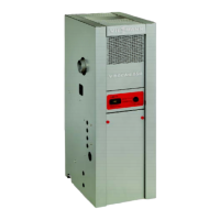
Standard Equipment
H Wet bas e sectional cast iron heat
exchanger with stainless steel burners
H Induced draft blower and pressure
switch
H Electronic ignition
H 24 VAC redundant seat gas valve
H Boiler fully insulated with 1½”/38 mm
fiberglass wrap-around blanket
H Boiler control panel with adjustable
operating limit (122°F - 194°F), fixed
high limit (248°F) and temperature
gage
H Pump aquastat to turn pump on at
104°F / 40°C and off at 91°F / 33°.
H One 120/24 VAC transformer
H 30 psig pressure relief valve, pressure
gage and fittings
H One cleaning brush
Boiler comes standard equipped with
30 psig ASME-rated pressure relief
valve. This 30 ps ig pressure relief valve
may be exchanged at the job sit e with a
50 psig ASME-rated pressure relief
valveonlybystrictlyobservingthe
minimum relief valve capacity in lb/h
marked on the nameplate. The
maximum allowable working pressure is
50 psig.
Be aware that best overall performance
is achieved when all components are
properly sized. Sizing of the required
circulation pump according t o the pipe
layout and calculation of a proper
volume expansion tank is vital to obtain
the system’s peak performance.
5167 450 v1.4