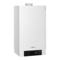
Do you have a question about the Viessmann Vitodens 100-W WB1B Series and is the answer not in the manual?
| Heat Exchanger Material | Stainless steel |
|---|---|
| Type | Wall-mounted condensing boiler |
| Efficiency | Up to 98% |
| Fuel | Natural gas or LPG |
| Modulation Range | 1:6 |
| Flue Gas Connection | 60/100 mm |
| NOx Emissions | Less than 40 mg/kWh |
| Warranty | 5 years |
| Water Pressure | Max. 3 bar |
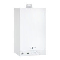
Wall-Mounted, gas-fired condensing boiler with optional on demand hot water CombiPLUS Kit.
Ensures understanding of instructions to prevent damage, injury, and loss of life.
Notes on symbols and notations for hazards and important product information.
Details required clearances for installation and service of the boiler and CombiPLUS.
Instructions for proper venting installation and requirements.
Details on connecting electrical components for the power/pump module.
Lists essential tools for testing, analysis, and cleaning.
Guides through identifying and resolving faults using diagnostic tables.
Provides specifications, ratings, and connection details for the boiler.
Explains symbols and notations for hazards and product information.
Details boiler serial number requirements and compatibility checks.
Describes boiler type, operation, and factory settings.
Specifies requirements for the installation location and ambient conditions.
Ensures all necessary accessories are installed before placing the boiler.
Details required clearances for installation and service of the boiler and CombiPLUS.
Illustrates different installation configurations for the CombiPLUS unit.
Overview of piping connections for the boiler.
Provides detailed dimensional drawings of the boiler.
Details piping and connection points for the CombiPLUS unit.
Diagrams showing factory supplied piping connections for specific models.
Instructions for mounting the boiler and CombiPLUS on various wall types.
Details on installing mounting brackets for wood and metal studs.
Steps for mounting the boiler onto the wall bracket.
Overview of boiler connections, starting with flue gas.
Details on proper piping practices and gas connection.
Procedures for performing a leak test on the gas supply piping.
Instructions for flushing and connecting the boiler to the heating system.
Details on connecting the condensate drain and filling the siphon.
Covers installation of safety devices and pressure testing procedures.
Step-by-step guide for hydrostatically pressure testing the boiler.
Diagrams showing CombiPLUS connections and pipe lengths.
Instructions for installing fittings and system connections to the CombiPLUS.
Procedure for exchanging the flow restrictor for specific models.
Steps for preparing the wall and mounting the CombiPLUS unit.
Instructions for connecting the CombiPLUS to the boiler using flex pipes.
Details on routing control and pump cables for the CombiPLUS.
Steps for removing covers to access boiler and power pump module controls.
Procedure for preparing the power pump module for CombiPLUS wiring.
Guide for connecting CombiPLUS cables to the boiler's power pump module.
Instructions for reassembling covers of the power pump module, boiler, and CombiPLUS.
Procedure for installing the DHW pressure relief valve and scald danger label.
Steps for programming the boiler control for operation with or without CombiPLUS.
Provides schematics and guidelines for system layouts.
Specifies minimum clearances from non-insulated pipes to combustible construction.
Graph showing pressure drop in the primary circuit based on flow rate.
Recommended heating pumps for Vitodens 100-W models.
Details on the Grundfos UPS15-78 pump performance and specifications.
Diagram for a single heating circuit system with Vitodens 100-W.
Diagram for a system with DHW storage, low-loss header, and one heating circuit.
Diagram for a system with DHW storage, closely spaced tees, and one heating circuit.
Diagram for a complex system with multiple circuits and controllers.
Detailed wiring schematic for System Layout 4.
Details on heating circuits, DHW production, and low-loss header use.
Diagram for a system with CombiPLUS and one heating circuit.
System layout with CombiPLUS, low-loss header, and one heating circuit.
System layout with CombiPLUS, no low-loss header, and one heating circuit.
Instructions for connecting the boiler in a heating/cooling system.
Diagrams for installing a low water cut-off device for the boiler.
Details on optional accessories like neutralization units and low-loss headers.
Information on low-loss header types, benefits, and installation principles.
Guidance on vent termination and protection against environmental effects.
Steps to open the control unit and power/pump module.
Wiring details for room thermostat, DHW, and pump connections.
Explanation of OpenTherm protocol and its connection to the boiler.
Procedures for closing modules and reinstalling the control unit.
Steps for reattaching the front panel to the boiler.
Lists essential tools for testing, analysis, and cleaning.
Identifies and explains the boiler's controls, indicators, and display elements.
Diagram identifying major components within the boiler assembly.
Diagram identifying major components within the CombiPLUS unit.
Outlines the sequence for start-up, inspection, and maintenance procedures.
Detailed steps for filling and venting the heating system with water.
Ensures correct 120 VAC power supply and neutral conductor connection.
Guides selection of gas type (natural gas or LPG) based on specifications.
Procedures for measuring gas static and running pressure.
Details on measuring running gas pressure at the test nipple.
Explanation of the premix combustion system and burner operation.
Procedure for performing relay tests and checking CO2 levels.
Steps for adjusting high-fire and low-fire CO2 content.
Procedure for setting the boiler for operation at high altitudes.
Procedure for limiting the maximum heating input or output.
Method for verifying input by timing the natural gas meter.
Ensuring all system connections are pressure-tight and leak-free.
Guidance on taking CO2 measurements before and after gas appliance work.
Performing a simplified leak test on the venting system.
Steps for removing the front panel for access to measurement ports.
Procedure for safely removing the burner assembly.
Instructions for inspecting and replacing burner gasket and cylinder assembly.
Guidance on checking, cleaning, and adjusting ignition and ionization electrodes.
Procedure for checking and cleaning the condensate drain and siphon.
Procedure for checking pH and replacing granulate in the neutralization unit.
Instructions for cleaning combustion chamber and heat exchanger surfaces.
Procedures for checking expansion tank pressure and system fill pressure.
Ensures proper operation of safety valves, pressure relief valve, and pump(s).
Ensures gas supply piping and fittings are leak-tight.
Steps for reinstalling the burner assembly after service.
General steps to diagnose and correct system faults.
Adjusting room temperature settings and boiler water temperature.
Flowchart detailing start-up sequence and common faults.
Table listing fault codes, causes, and corrective measures.
Procedure for resetting faults using the control unit selector dial.
Steps for removing the front panel and checking the boiler temperature sensor.
Procedure for checking the outdoor temperature sensor and frost protection function.
Guides for setting boiler water temperature based on controls.
Procedure for checking and replacing the fixed high limit safety device.
Procedure for checking and replacing the flue gas temperature sensor.
Instructions for checking and replacing fuses in the control and power pump modules.
Troubleshooting steps specific to the CombiPLUS unit.
Procedure for checking the CombiPLUS outlet temperature sensor.
Steps for replacing the flow limiter in the CombiPLUS unit.
Procedure for checking and replacing the plate type heat exchanger.
Details on connecting accessories like outdoor sensors and OpenTherm to terminal strips.
Provides technical specifications and data for the boiler and CombiPLUS.
Table detailing priority levels for different operating controllers.
Contains detailed specifications, dimensions, and connection sizes.
Provides flue gas values, condensate rates, and noise levels.
Lists DHW supply temperatures, draw rates, pressures, and dimensions.
Diagram and table outlining the burner's operational sequence.
Detailed explanation of each phase in the burner's operational sequence.
Comprehensive wiring diagram for natural gas and propane operation.
Table detailing activation sequences for service functions like filling and relay tests.
Lists parts for the Vitodens 100-W boiler and ordering information.
Diagram and list of boiler components and their part numbers.
Lists control unit parts, wiring harnesses, and installation fittings.
Lists CombiPLUS Kit parts, accessories, and installation fittings.
Lists parts for the CombiPLUS unit, including regulators and bypass cartridges.
Template for recording static pressure, gas pressure, and CO2 measurements.
Safety instructions and steps for lighting and operating the appliance.





 Loading...