Additional Information
47
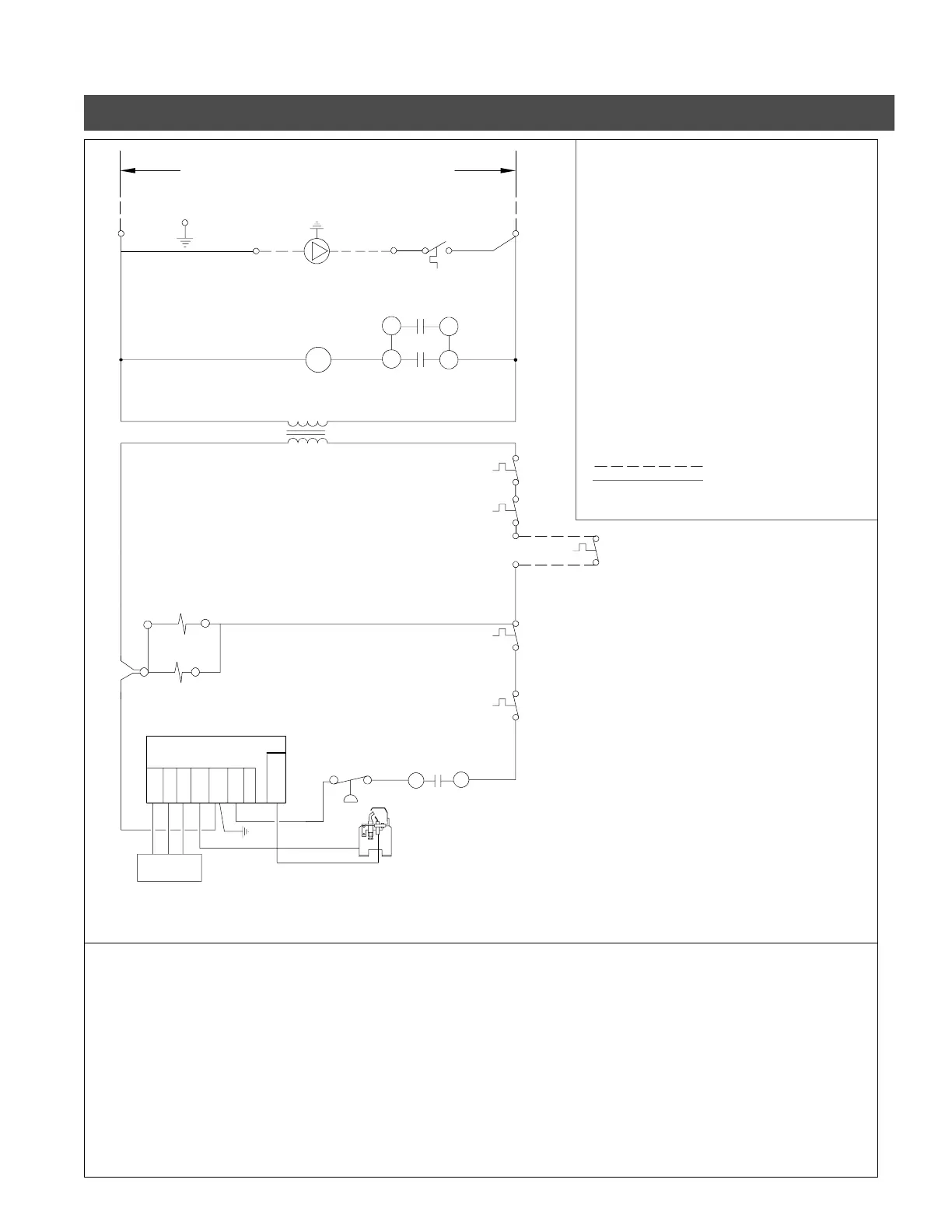
Ladder Diagram - Vitogas 050, ECV with Honeywell Intermittent Pilot
24 V
L
N
VALVEGAS
S8600(H,M)
HONEYWELL
M
4
5
SEQUENCE OF OPERATION
1. Thermostat calls for heat.
2. Relay and sequencer are energized with 24V.
7. Provided FRS is closed (not activated)
and pressure switch has remained closed,
pilot will spark, light and prove flame,
allowing main burner to operate.
8. Pilot and main burner will cycle off
thermostat or other operating control
is satisfied.
SHL1
Adjustable high limit aquastat
(Maximum setting 194°F)
SHL2
Manual reset aquastat
(Fixed setting 248°F)
PA
Pump Aquastat
Pump on at 40°C (104°F)
Pump off at 33°C ( 91°F)
FRS Flame roll-out switch
R1
24V Relay
S1 Sequencer
C1S
C1R N.0. contact
N.O. contact, upper stage marked
C2S
4,5
N.O. contact, lower stage marked
1,3
24V
PS
Pressure Switch 24V
Fan Induced draft blower motor
assembly
FIELD WIRING
FACTORY WIRING
3. Relay contacts close.
4. Fan is energized with 120V.
5. Fan develops sufficient pressure to
close pressure switch.
6. After 30 second prepurge, contacts 1,3
of sequencer close allowing 24V to
ignition system.
SHL1 aquastat setting until
1
of relay 1
1
3
Use external relay if pump exceeds 4A.
delay on break
delay on make
120V, 60 Hz Less than 12A
and make
and break
G
will de-energize, burner will stop and there
will be a fan post purge of 50 seconds
through contacts 4,5 of sequencer.
9. Thermostat is satisfied, ignition system
SHL1, SHL2 are closed.
MV
PV
MV PV GND
BRN
24V
GND
24V
SPARK
Pump 120V
4A max.
Blower motor
Transformer
120V
24V
40VA
Class 2
Ignition
cable
PS C2S
R1
S1
FRS1
FRS2
SHL1
SHL2
Q3451A
pilot burner
C1R
C1S
PA
12
1
2
24V Room
thermostat or other
operating control
Anticipator
setting: 0.9A
Caution: Label all wires prior to
disconnection when servicing controls. Wiring
errors can cause improper and dangerous
operation. Verify proper operation after s erv icing.
Note: Burner should not activate
if pressure tube is disconnected from pressure
switch.
Refer to wiring label affixed to boiler access
panel. Vies smann reserv es the right to
substitute components or wiring methods.
Boiler wiring label takes precedence.
Do not connect any external load to the boiler
24V transformer. Use external power source
to power zone valves.
Do not operate boiler without high limit aquastats
wiredincontrolunit.
5167 450 v1.4