13
aVG
X6
15
1
5
11
F0
F2
4
B
aVG
D
4 3 2 1
X5
X2
A
C
N
?
3
2
1
N N N N
1
? ? ?
123
X6
X1
X2
123
sYÖsYAsYSsYD
4 1235
G
F E
12
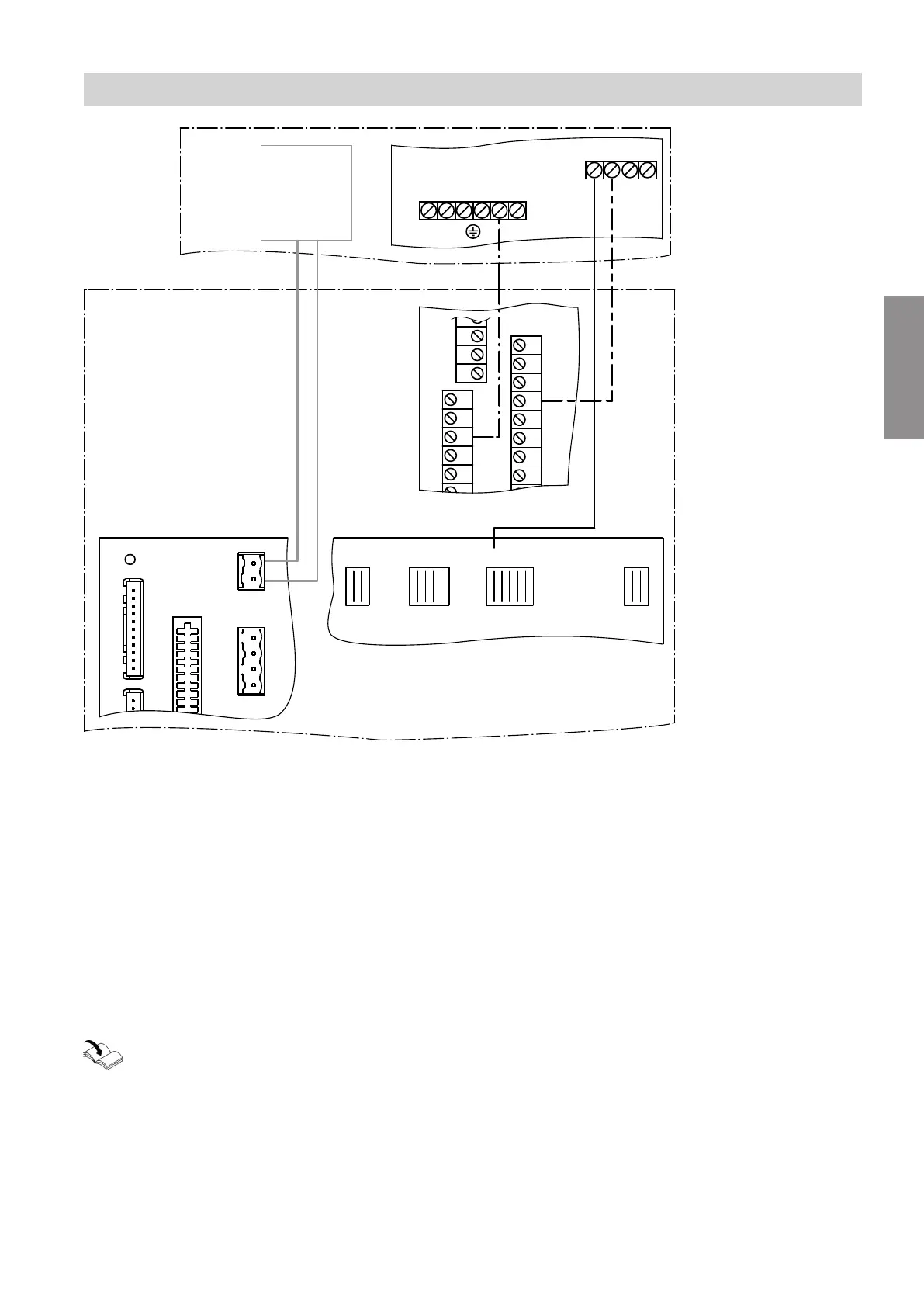
Fig.6
A
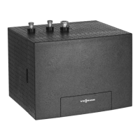
NC-Box
B
Mixer extension kit
aVG
KM BUS to the heat pump control unit or to
the KM BUS distributor in the case of several
KM BUS subscribers
C
NC-Box terminal box
X2 230 V~ terminal strip
■
Power supply 1/N/PE 230 V/50 Hz across
X2.1 and X2.2 via on-site power distribution
board
■
Switching the NC-Box (NC signal) across
X2.3 and X2.4 by the heat pump control unit
X5 Earth conductor terminal strip
D
Cross connect PCB or luster terminals
X1 Earth conductor terminal strip
X2 Neutral conductor terminal strip
E
Main PCB (function components 230 V~)
F
Controller and sensor PCB
G
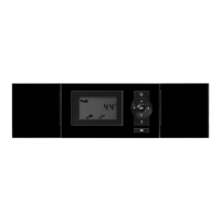
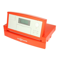
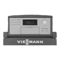
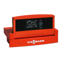
Vitotronic 200 heat pump control unit
"Vitotronic 200" service instructions
Installation sequence
Electrical connection (cont.)
5675 869 GB
Installation