5
For
■
Vitocal 222-G/242-G and Vitocal 333-G/343-G
■
Vitocal 200-G, Vitocal 300-G and Vitocal 350-G with-
out sufficient installation space above the heat
pump, e.g. when retrofitting
1. Fit the NC-Box near the heat pump on a wall capa-
ble of bearing the load.
2. Connect on-site connection lines so that they are
free of load and torque stress.
Hydraulic connection with hydraulic connection set
Vitocal 200-G, Vitocal 300-G and Vitocal 350-G with
sufficient installation space above the heat pump: See
page 7.
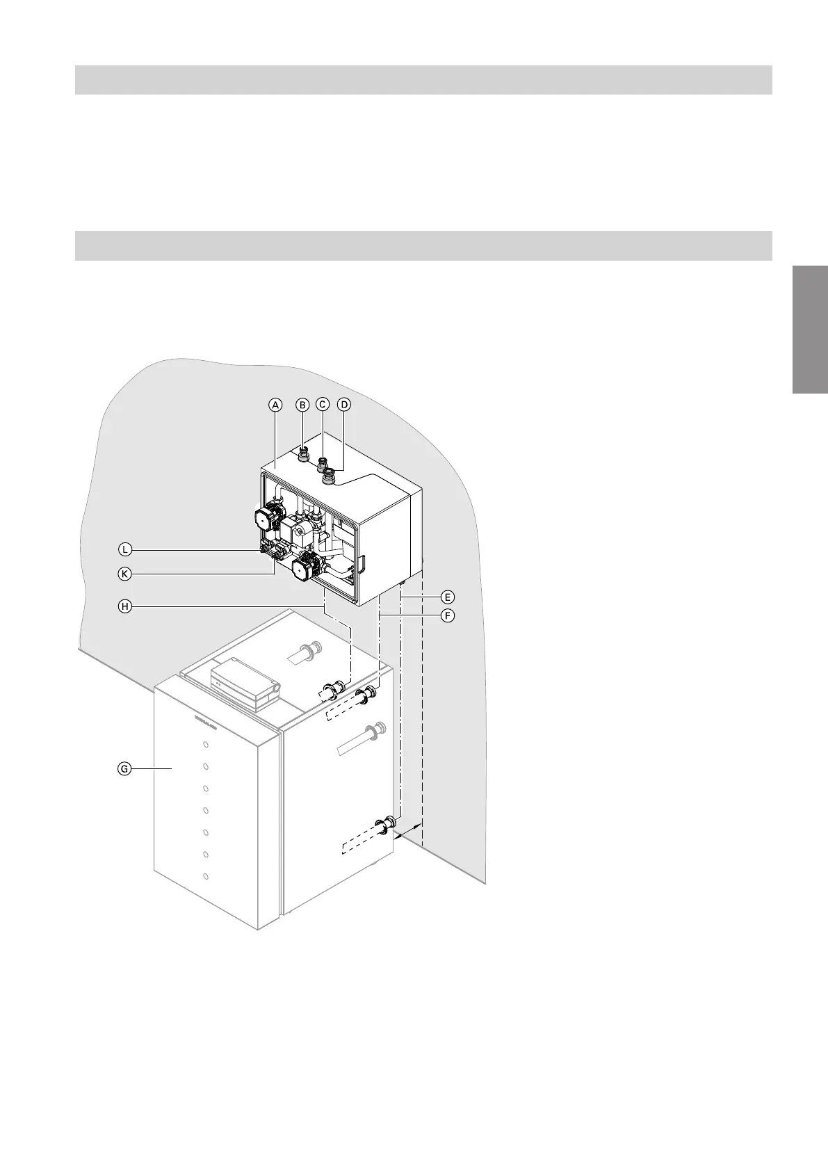
Fig.1
A
NC-Box
B
Return, heating/cooling circuit or separate cooling
circuit
C
Flow, heating/cooling circuit or separate cooling
circuit
D
Primary circuit flow (NC-Box brine entry)
E
Secondary circuit return to heat pump
F
Secondary circuit flow to the NC-Box
G
Heat pump
H
Primary circuit flow (heat pump brine inlet)
K
Primary circuit BDF valve (brine)
L
Secondary circuit BDF valve (heating water)
Preparing for installation
Hydraulic connection with on-site pipework
5675 869 GB
Installation