15
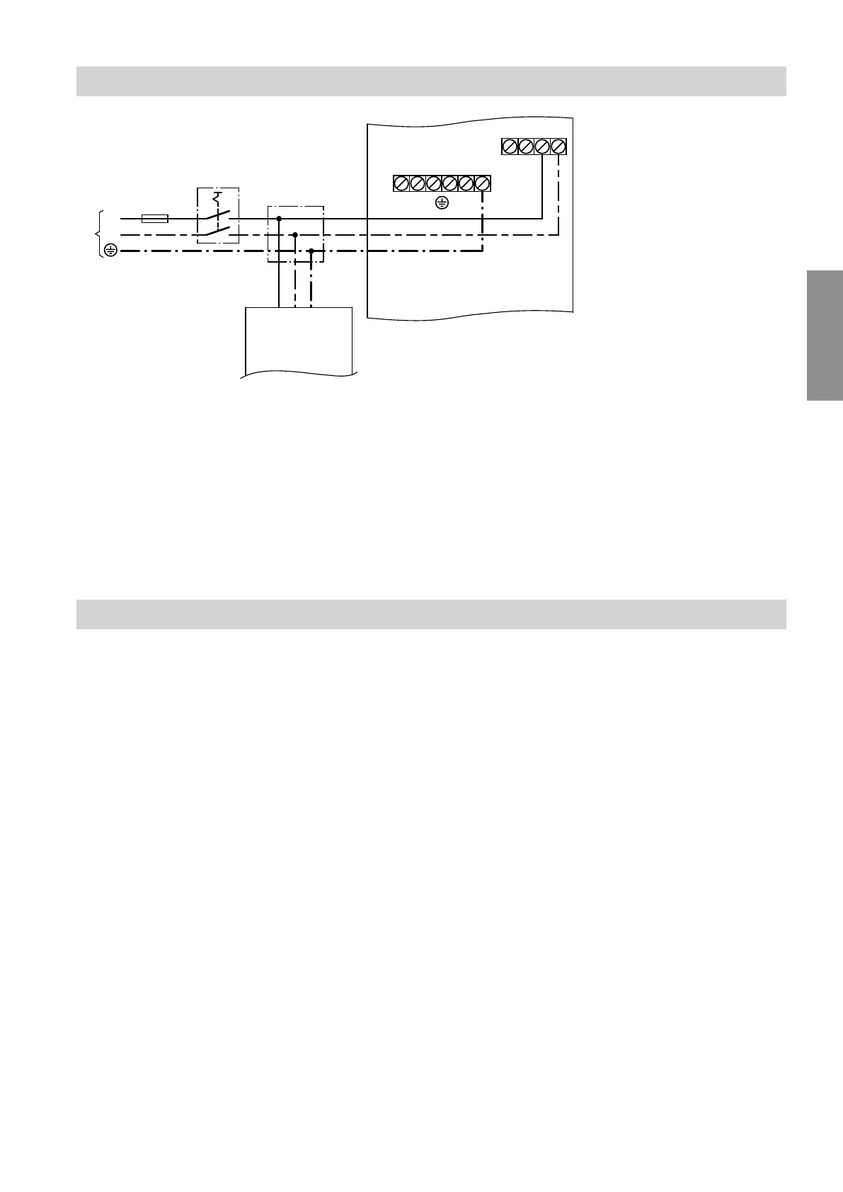
Fig.7
A
NC-Box terminal box
X2 230 V~ terminal strip
■
Power supply 1/N/PE 230 V/50 Hz across
X2.1 and X2.2 via on-site power distribution
board
■
Switching the NC-Box (NC signal) across
X2.3 and X2.4 by the heat pump control unit
X5 Terminal strip for earth conductor
B
Power distribution board (on-site)
C
Heat pump control unit
D
Mains isolator (optional)
E
Fuse F1 (max. 16 A)
F
Power supply 1/N/PE 230 V/50 Hz
Closing the NC-Box
Fit in reverse order to Fig. 3 on page 8.
Installation sequence
Power supply (cont.)
5675 869 GB
Installation