1L1
3L2
5L3
1
3NO
A1
2T1
4T2
6T3
14NO
A2
3
2
1
4
3
2
1
KM
L
L
L
4
6
1
1
2
2
3
3
42
43
41
5
C
2
TH2
C
1
TH1
8
7
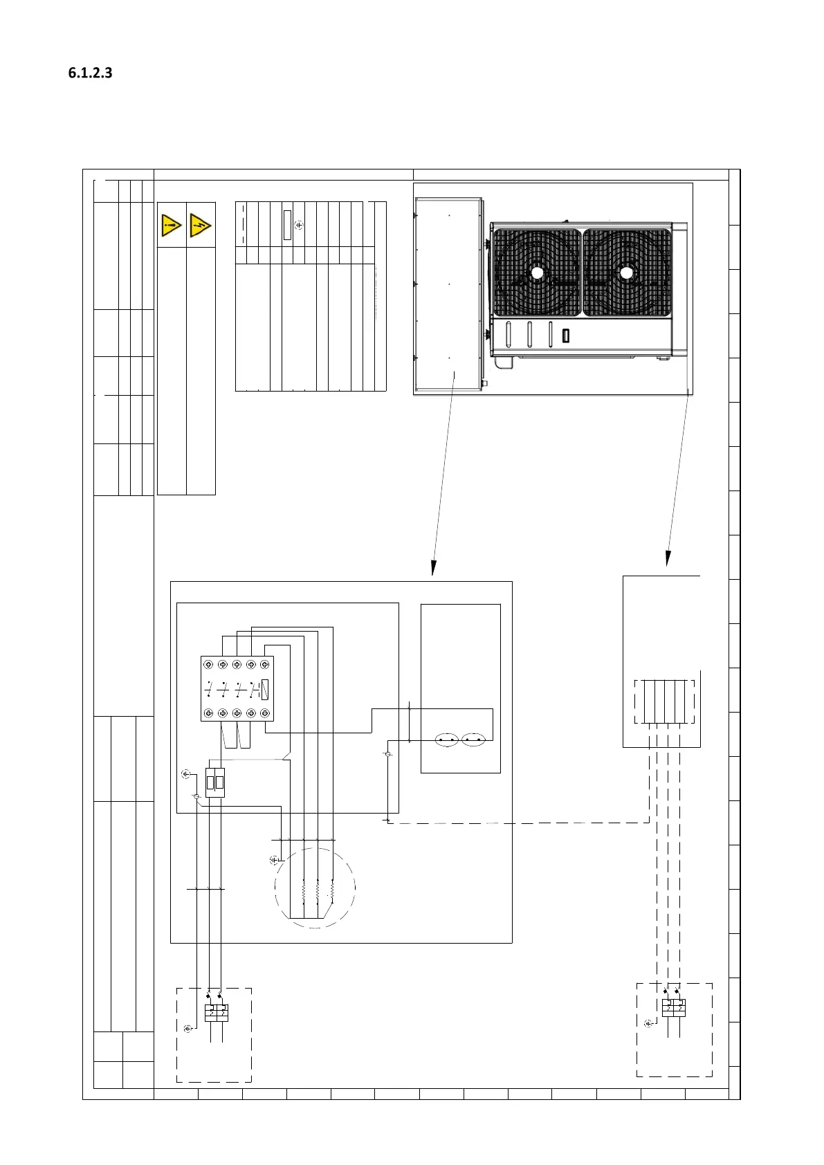
Rete / Mains
230Va c
1Ph-N-PE
50Hz
I
d
L
I
d
N
PE
PE
L
N
QD1
L
N
PE
ACT
Internal Terminal Block
i-32V5 / i-HWAK V4
Heating Resistor [2-3-4,5 kW]
7
NOTE da leggere prima dell'installazi one
NOTES Read before installation
Componente
Component
Note
Descrizione
Description
QD1
#
Int errutto re di dispersione verso terra /
Earth leakage circuit breaker
QD2
#
Int errutto
re di dispersione verso terra /
Earth leakage circuit breaker
KM
Contatto re /
Contactor
QE1
Quadro elettrico 1 /
Swit chboard 1
QE2
Quadro elettrico 2 /
Swit chboard 2
Punto di massa /
Point of ground
Morsetto a molla /
Spring terminal
Th1
Termostato automatico di sicurezza /
Automatic Safety Thermostat
Th2
Termostato manuale di sicurezza
/
Manual Safety Thermosta t
F1
Fusibili /
Fuses
Collegamenti a cura dell'installatore /
Connections by the inst aller
AEH
# Da reperire in loco / Obtain locally
X-6.1
QE2
Rete / Mains
230Va c
1Ph-N-PE
50Hz
I
d
L
I
d
N
PE
QD2
i-32V5 / i-HWAK V4
E' obbligatorio Installare, a monte d i ogni unità, un idoneo dispositivo di protezione e sezionamento dell'energia
elettrica con curva caratte ristica ritardata, con un adeguato potere di interruzione e protezione diff erenziale.
Obligation to install, in front of each unit, a suitable protective device and disconn ection of electricity with delayed
characteristic curve, with an adequate breaking and differential protection .
La legenda e lo schema riportano simboli non necessariamente presen t i nel circuito
The legend and diagram shows symbols not necessarily present in the circuit
ACT
QE1
5
W1
W2
N
41
W3
PE
W4
L
PE
F1
F1
Fuses R 2 kW:
2 x 10 A
10.3x38 gG
Fuses R 3-4,5 kW:
2 x 20 A
10.3x38 gG
#
#
2 431 5 6 7 8
9 10 11
12 13 14 15 16 17
18
1900
A
2 431 5 6 7 8
9 10 11
12 13 14 15 16 17
18
1900
B
C
D
E
F
G
H
I
J
K
L
M
01 Sistemazione fil i 13/ 11/2019
00 First emission 05/0 6/ 2017 A.B. A.B. A.B.
Rev
Item
Descrizione modifiche
Description of changes
D a ta
Date
Disegnato
Drowing by
Verificato
Verif ied by
Approvato
Approved by
Titol o / Title Schema elettrico ACT 1ph R 2-3-4,5 kW
Codice / Code
Ogget
to / Ob
ject Sc
he ma elettr
ico / Electr ic
al
drawing
Foglio
Sheet
1
di
of
1
Tutt e le inform
azion i con t enut e nel presente do cument o sono di prop rietà esclusi
va d ella Advan tix s.p.a e non po ssono essere r iprod ot te, divulga te o
com unqu e ut i
lizzate senza la sua prev ent iva a utorizzazione scrit t a. La societ à p ro
priet ar ia tutela i pro pri d irit t i a norm a di legg e
All tecnical information contained in this document is exclusive pro pert y of Advantix s.p.a. and may neither be used nor disclosed
withou t its prior writen con sent. The society will guard own rights by law in for ce
Mod. ADV.00
M.P. A.B. A.B.
02
Aggiornamento
16/ 06/ 2020
K.G. A.B. A.B.