1L1
3L2
5L3
13NO
A1
2T1
4T2
6T3
14NO
A2
F1
F2
F3
3
2
1
3
2
1
13
12
11
KM
L3
L2
L1
N
6
1
1
2
2
3
3
42
43
41
5
C
2
TH2
C
1
TH1
8
7
R
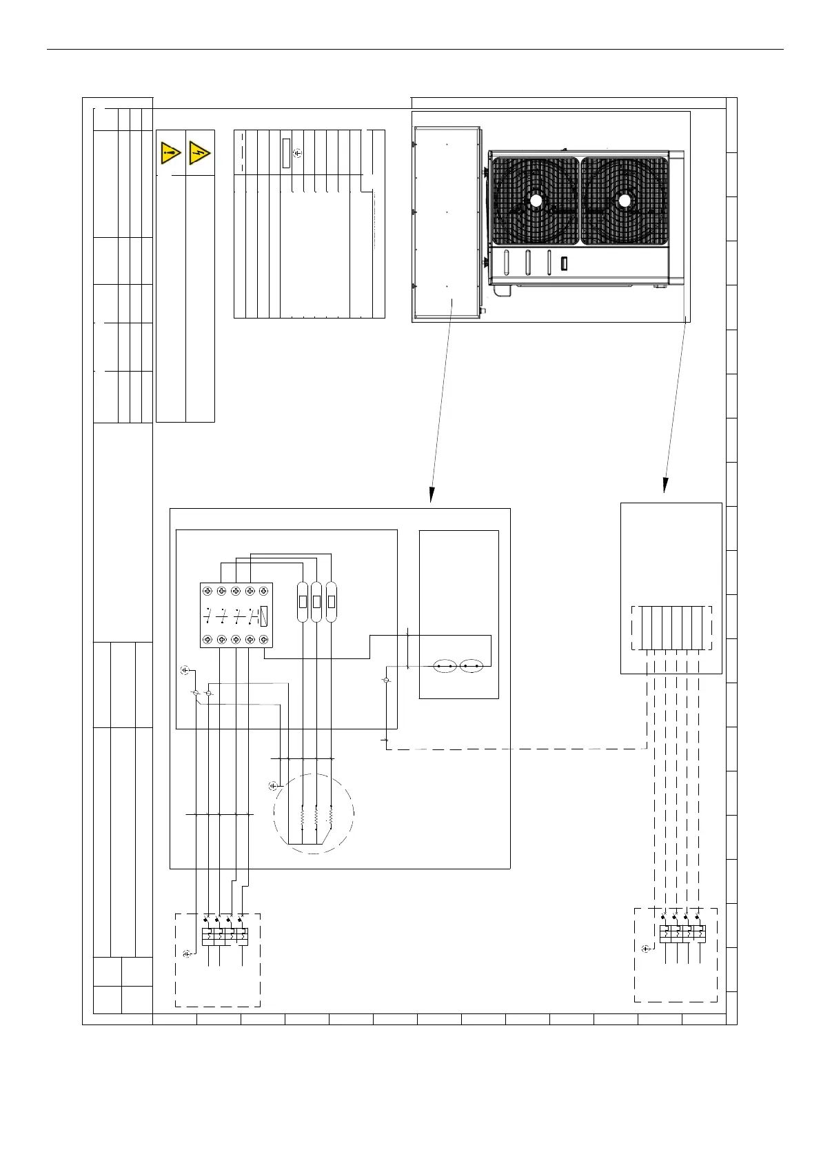
ete / Mains
400Va c
3Ph-N-PE
50Hz
PE
PE
L1
N
L1
N
PE
ACT
Internal Terminal Block
i-32V5 / i-HWAK
V4
Heating Resistor [2-3-4,5 kW]
7
NOTE da leggere prima dell'installazione
NOTES Read before installation
Componente
Component
Note
Descrizione
Description
QD1
#
Int errutto re di dispersione verso terra
/
Earth leakage circuit breaker
QD2
#
Int errutto re di dispersione verso terra
/
Earth leakage circuit breaker
KM
Contatto re
/
Contactor
QE1
Quadro elett rico 1
/
Swit chboard 1
QE2
Quadro elett rico 2
/
Swit chboard 2
Punto di massa
/
Point of ground
Mor
setto a mol la
/
Spring terminal
Th1
Termostato automatico di sicurezza
/
Automatic Safet y Thermostat
Th2
Termostato manuale di sicurezza
/
Manual Safety Thermost at
F1-F2-F3
Fusibili
/
Fuses
Collegamenti a cura del l'inst al latore
/
Connections by the installer
AEH
# Da reperire in loco / Obtain locally
X-6.1
QE2
Rete / Mains
400Va c
3Ph-N-PE
50Hz
I
d
L1
I
d
N
PE
QD2
i-32V5 /
i-HWAK V4
E' obbligatorio installare, a monte di ogni unità, un idoneo dispositi vo di protezione e sezionamento dell'energia
elettrica con curva caratteristica ritardata, con un adeguato potere di interruzione e protezione diff erenzia le.
Obligation to install, in front of
each unit , a
suitable protective device and discon
nection of electricity wit
h delayed
characteristic curve, with an ad
equate brea
king and differential prot ection .
La legenda e lo schema riportano simboli non necessariamente presenti nel circuito
The legend and diagram show s symbols not necessarily present in the circuit
ACT
QE1
5
W1
W2
N
W3
PE
W4
PE
I
d
L3
I
d
L2
I
d
L1
I
d
N
QD1
I
d
L3
I
d
L2
#
#
L2
L3
L2
L3
41
Fuses R 2 kW:
3 x 4 A 5x20 F
Fuses R 3-4,5 kW:
3 x 8 A 5x20 F
2 431 5 6 7 8 9 10
11 12 1
3 14 15 16 17 18 1900
A
2 431 5 6 7 8 9 10
11 12 1
3 14 15 16 17 18 1900
B
C
D
E
F
G
H
I
J
K
L
M
01
Sis temazione fili
13/11/2019
00 First emission 05/06/2017 A.B. A.B. A.B.
Rev
Item
Descrizione modifiche
Description of changes
D a ta
Date
Disegnato
Drowing by
Verificato
Verif ied by
Approvato
Approved by
Titol o / Tit
le
Schema elettrico ACT 3ph R 2-3-4,5 kW
Codice / Cod
e
Oggetto / Object Schema elettrico / Electr ical drawing
Foglio
Sheet
1
di
of
1
Tutt e le inf ormazion i contenu te nel presente docu ment o sono di pro prietà esclusiva della Adv antix s.p.a e non po ssono essere riprod ot t e, divu lgat e o
com unqu e utilizzate senza la sua p rev ent iva aut o rizzazion e scritt a. La societ à prop rietaria tut ela i propri dirit t i a n orma di legge
All tecnical infor m
ation cont ained in this do cume nt is exclusive prop erty of Advantix s.p.a. and may neither b e used nor d isclosed
witho ut its pr ior w
riten consent. The society will gua rd o wn righ ts by law in force
Mod. ADV.00
M.P. A.B. A.B.
02
Aggiornamento
16/06/2020
K.G.
A.B. A.B.