1L1
3L2
5L3
13NO
A1
2T1
4T2
6T3
14NO
A2
3
4
3
1
KM
6
Ret
e / Mains
230Vac
1
Ph-N-PE
50Hz
I
d
L
I
d
N
PE
PE
L
N
QD1
L
N
PE
ACT
Internal Terminal Bl
ock
i-32V5 / i-HWAK V4
Heating Resistor [1,2 kW]
NOTE da leggere prima dell'inst allazione
NOTES Read before inst allation
Componente
Component
Note
Descrizione
Description
QD1
#
Interruttore di dispersione verso terra
/
Earth leakage circ
uit breaker
QD2
#
Interruttore di dispersione verso terra
/
Earth leakage circuit breaker
KM
Contattore
/
Contacto r
QE 1
Quadro elettrico 1
/
S
witchboard 1
QE 2
Quadro elettrico 2
/
Swit chboard 2
Punto di massa
/
Point of ground
Morsetto a molla
/
S
pring terminal
Th1
Termostat o automatico di sicurezza
/
Automatic Safety Thermosta t
T
h2
Termostat o manuale di sicurezza
/
Manual Sa fety Thermostat
F1
Fusibili
/
Fuses
Collegamenti a cura dell'installatore
/
Connections by the installer
AEH
# Da reperire in loco / Obta in locally
X-6.1
AEH
QE1
Rete / Mains
230Vac
1Ph-
N-PE
50Hz
I
d
L
I
d
N
PE
QD2
i-32V5 / i-HWAK V4
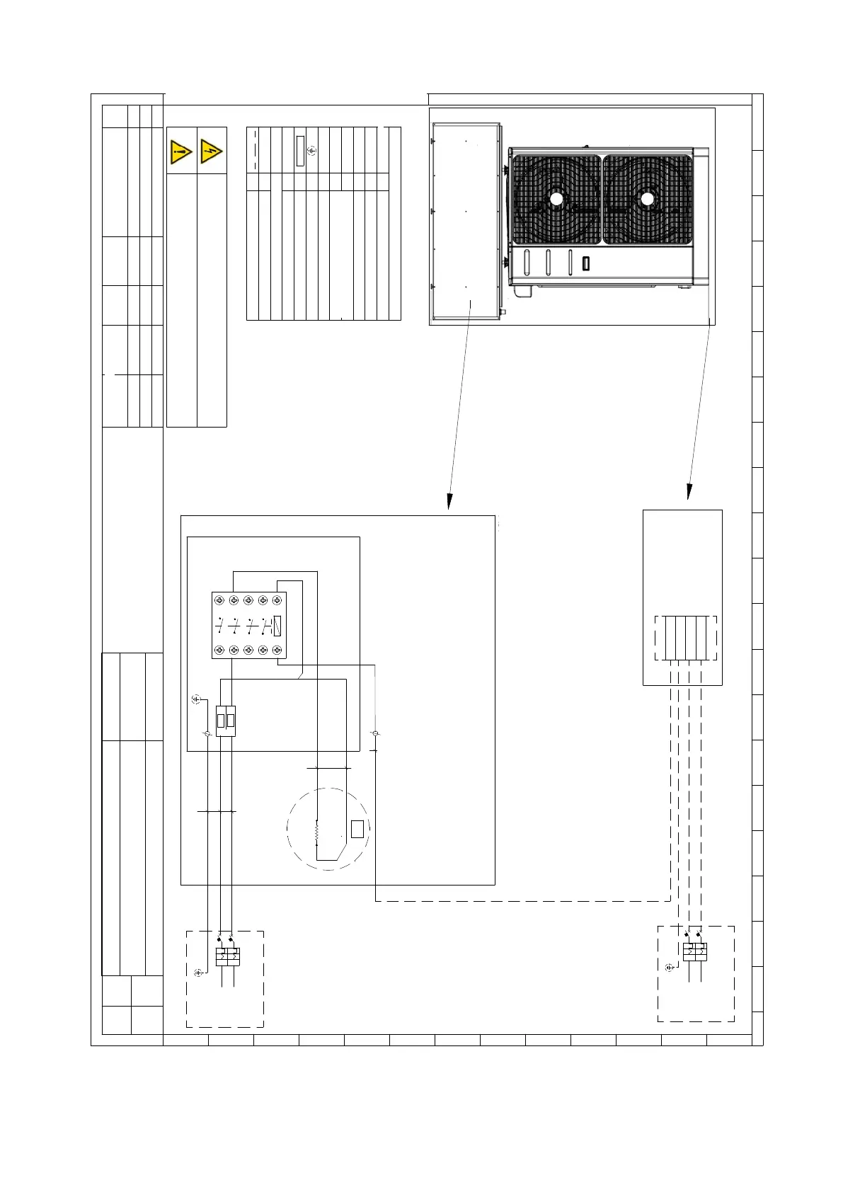
E' obbligato r io installare, a monte di ogni unità, un idoneo dispositivo di protezione e sezionamento dell'energia
elettr ica con curva caratteristica rita rdata, con un adeguato potere di interruzione e prote zione diff erenziale.
Obligat ion to install, in f ront of each unit, a suitable prot ective device and disconnection of electricity with delayed
characteristic curve, wit h an adequa
te breakin
g and diffe rential prote ction .
La leg enda e lo schema riportano sim
boli non
necessariamente presenti nel circuito
The legend and diagram shows symbo ls not necessarily present in the circuit
ACT
L
N
L
T
W2
L
N
PE
W4
W3
N
PE
L
F1
Fuses:
2 x 6 A
10.3x38 gG
F1
#
#
2 431 56789 10 11 12 13 14 15 16 17 18 1900
A
2 431 56789 10 11 12 13 14 15 16 17 18 1900
B
C
D
E
F
G
H
I
J
K
L
M
01 Revisione fili 26/11/2019 M.P. A.B. A.B.
00 First emission 05/06/2017 A.B. A.B. A.B.
Rev
Item
Descrizione modifiche
Description of changes
Data
Date
Disegnato
Drowing by
Veri ficato
Verified by
Approvato
Approved by
Titolo / Title
Schema elettrico ACT R 1,2 kW
C
od ice / Code
Ogg ett o / Object Schema elettrico / Electrical drawing
Foglio
Sheet
1
di
of
1
Tutt e le i
nfo rmazioni con tenu te nel p resent e docum ent o sono di prop rietà es
clusiva d ella Advant ix s.p.a e no n po ssono essere riprodo tte, divulga te o
com unq ue utilizzate sen za la sua preventiv a aut orizzazion e scritta. La societ à proprieta ria tut ela i propri diritt i a no rma di legg e
Mod. ADV.00
02
Aggiornamento
16
/06/2020
K.G. A.B
. A.B.
All tecnical infor mation con tained in this document is exclusive prop erty of Advantix s.p.a. and may neither b e used nor disclosed
withou t its pr
ior writen consent. The society will guard o wn righ t s by law in for ce