Index
1. Principles 1.1 Yielding heating energy from the ambient air ............................................................... 4
1.2 Operating mode ............................................................................................................ 4
1.3 Noise development ....................................................................................................... 6
■ Sound ....................................................................................................................... 6
■ Sound power level and sound pressure level ........................................................... 6
■ Transmission of sound in buildings ........................................................................... 7
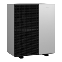
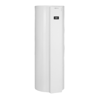
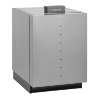
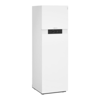
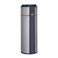
2. Vitocal 160-A 2.1 Product description ....................................................................................................... 8
■ Use ........................................................................................................................... 8
■ Output ....................................................................................................................... 8
■ Benefits ..................................................................................................................... 8
■ Delivered condition ................................................................................................... 8
2.2 Specification ................................................................................................................. 10
■ Specification ............................................................................................................. 10
■ Sound transmission data .......................................................................................... 10
■ Air flow rate curve ..................................................................................................... 11
■ Dimensions ............................................................................................................... 11
3. Extract/expelled air pipework 3.1 Expelled air apertures ................................................................................................... 12
■ Outside air inlet grille (external wall connection) ...................................................... 13
■ Expelled air roof outlet .............................................................................................. 13
3.2 Ventilation and extract air apertures ............................................................................. 13
■ Extract air valve DN 100 ........................................................................................... 13
■ Kitchen extract air valve DN 100 .............................................................................. 14
■ Extract air filter (G3) .................................................................................................. 14
■ Ventilation air element wall/external connection DN 100 .......................................... 14
■ Ventilation air filter (G3) ............................................................................................ 14
3.3 Sound insulation and silencer ....................................................................................... 14
■ Silencer DN 160, round, flexible ............................................................................... 15
3.4 Pipework and moulded parts ........................................................................................ 15
■ Flexible pipe DN 160, thermally insulated ............................................................... 15
■ Flexible pipe, compressed ........................................................................................ 16
■ Connecting piece ...................................................................................................... 16
■ Spiral-seam tube ....................................................................................................... 16
■ Bend 90° ................................................................................................................... 16
■ Bend 45° ................................................................................................................... 17
■ Tee ............................................................................................................................ 17
■ Tee, reduced ............................................................................................................. 17
■ Reducer 160/125 ...................................................................................................... 17
■ Reducer 125/100 ...................................................................................................... 18
4. DHW cylinder accessories 4.1 Safety equipment to DIN 1988 ..................................................................................... 18
5. Accessories for operation with
solar collectors (type WWKS)
5.1 Solar collectors ............................................................................................................. 18
6. Design information 6.1 Positioning .................................................................................................................... 18
6.2 Sound and vibration insulation ..................................................................................... 20
6.3 Electrical connection ..................................................................................................... 20
6.4 Condensate drain ......................................................................................................... 21
6.5 Connection to a solar circuit (type WWKS) .................................................................. 21
■ Hydraulic diagram ..................................................................................................... 22
6.6 Connections on the DHW side ..................................................................................... 22
6.7 Ventilation mode (Vitocal 160-A for extract mode) ....................................................... 23
■ Airtight building envelope .......................................................................................... 23
■ Fire safety ................................................................................................................. 23
■ Applicability ............................................................................................................... 23
■ Operational cycle ...................................................................................................... 23
■ Operation with open flue combustion equipment ...................................................... 24
■ Standard ventilation for standard operation .............................................................. 24
■ Extract/expelled air pipework (accessory) ................................................................ 24
7. Sizing 7.1 Determining the pressure drop for the extract/expelled air pipework (Vitocal 160-A for
extract mode) ................................................................................................................ 26
■ Flow velocity ............................................................................................................. 27
■ Pressure drop diagram for ventilation elements and expelled air outlets ................. 28
■ Flow pressure drop in the pipework .......................................................................... 29
Index
2
VIESMANN
VITOCAL 160-A
5822 485 GB