9
D
13c
9
A
B
4 3 2 1
74
1 2
C
6 5 4 3 2 1
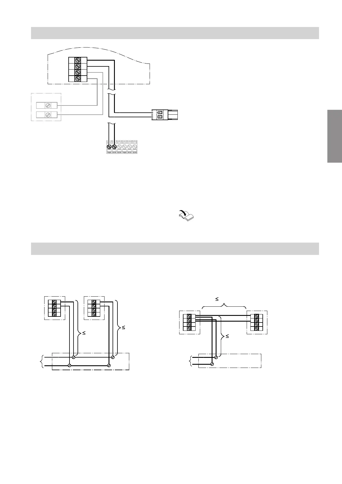
Fig. 2
A
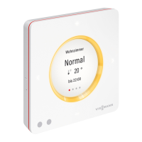
Vitotrol 200-E
B
2-pole plug
jF
(control unit with PlusBus distribu-
tor)
C
Plug & play plug with screw terminals for PlusBus
connection to heat generator
D
External room temperature sensor NTC 10 kΩ
(accessories)
Total length of all PlusBus cables max. 50 m. Connection to plug & play plug:
Heat generator installation and service instruc-
tions
Connecting several remote controls
Two Vitotrol 200-E can be connected to the same con-
trol unit.
Total length of all PlusBus cables max. 50 m.
Version 1
C
B B
A
15 m
15 m
4 3 2 1
4 3 2 1
Fig. 3
A
To the control unit (see connection diagram on
page 9)
B
Vitotrol 200-E
C
On-site junction box
Version 2
A
B
C
B
15 m
15 m
4 3 2 1
4 3 2 1
Fig. 4
A
To the control unit (see connection diagram on
page 9)
B
Vitotrol 200-E
C
On-site junction box
Installation sequence
Fitting and connecting the Vitotrol 200-E (cont.)
5839309
Installation