50
Connection and wiring diagram
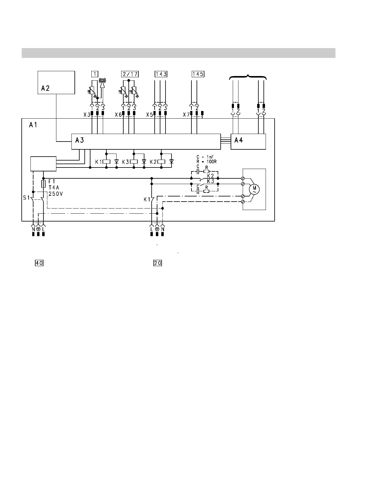
Connection and wiring diagram
A1 Main PCB
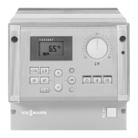
A2 Programming unit
A3 Supplementary PCB
A4 LON communication module (accessory)
or
Viessmann 2-wire-BUS communication module
(accessory)
F1 Fuse
K1 - K3 Relays
S1 ON/OFF switch
Plug 120 VAC
sÖ Heating circuit pump (accessory)
fÖ Power supply 60 Hz
Low voltage plug
! X3 Outdoor temperature sensor (accessory)
? X6 Supply temperature sensor
aJ X6 Return temperature sensor
aVDX5 External connections
aVGX7 KM-BUS-Participant
A LON or Viessmann 2-wire-BUS connection
This wiring diagram only applies in conjunction with Viessmann products.
5285 967 v1.2
A