32
Components
Components from the parts list
For parts list, see page 51.
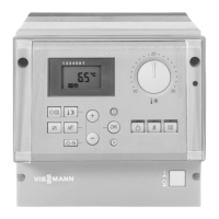
Main PCB
The main PCB comprises:
Relays and outputs for controlling pumps and the mixing
valve actuator
Sockets for connecting sensors, the incoming power
supply and the heating circuit pump
Low Volt supply
Fuse F1: 4 A,
max. power loss < 1.6 W
System ON/OFF switch
Slot for PCB, LON communication module, Viessmann
2-wire BUS communication module
Supplementary PCB
Microprocessor with software
When replacing the PCB:
1. Record the codings and adjustments made at the control
unit.
2. Replace the PCB.
3. Set codings 8A : 176 and
92 : 180.
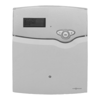
Programming unit
Setting the:
Heating program
Set values
Switching times
Heating curve
(slope and shift)
Date
Time
Displaying:
Temperatures
Operating conditions
Faults
Communication module Viessmann 2-wire BUS
PCB for data exchange with:
Vitotronic 300, Model KW3
Outdoor reset logic control unit for wall-mounted boilers
Cascade control for gas-fired wall-mounted boilers
Dekamatik system
The communication interruption will be displayed.
The rotary dial is factory pre-set to 4.
LON Communication module
PCB for data exchange with:
Vitotronic 200, Model GW1
Vitotronic 300, Model GW2
Vitocontrol-S VD2/CT3
additional Vitotronic 050
The communication interruption will be displayed.
5285 967 v1.2