Do you have a question about the Viking Access Systems G-5 and is the answer not in the manual?
Details the features and capabilities of the Viking G-5 swing gate operator.
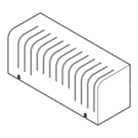
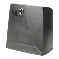
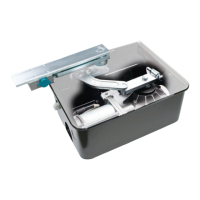
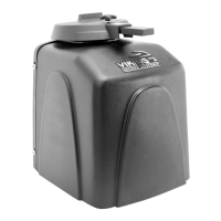
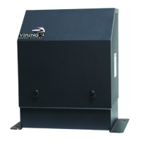
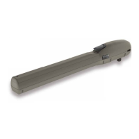
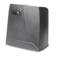
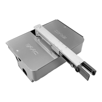
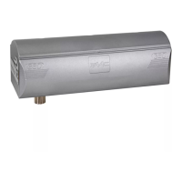
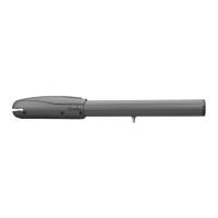
Visual breakdown of operator and controller components.
Identification and description of the control board terminals and indicators.
Crucial warnings and guidelines for safe installation and operation of the gate operator.
Defines classifications for gate operators based on usage and location.
Mandatory requirements for safety sensors to prevent entrapment hazards.
Covers pull-to-open and push-to-open installation configurations.
Step-by-step guide for physically mounting the gate operator unit.
Details the alternative post mounting kit for operator installation.
Procedure for setting the open and close limit positions for the gate.
Instructions for mounting the Electronic Control Unit (ECU) box.
Guide for connecting the operator to various power sources.
Wiring instructions for master (single) motor connections.
Wiring instructions for slave motor connections in dual-gate systems.
Explanation of limit LEDs and their meanings for gate position.
Configuration of core operator functions like speed, overlap, and timers.
Configuration of entrapment protection and integrated heater functions.
Guidance on interpreting LED indicators for diagnostics.
Guidance on interpreting LCD messages for diagnostics.
Information on connecting various safety and control accessories.
Best practices for installing vehicle detection loops.
Instructions for synchronizing operation with a Viking B-12 Barrier Arm.
Details on connecting access control devices to the control board.
Wiring diagrams for common radio receiver models.
Requirements and information for solar power integration.
Overview of optional Viking accessories and kits for enhanced functionality.
Summary of the gate operator's key features and technical specifications.
| Model | G-5 |
|---|---|
| Category | Gate Opener |
| Power Supply | 120VAC |
| Motor Type | DC |
| Remote Control Frequency | 433 MHz |
| Remote Control | Included |
| Battery | 12V 7Ah |
| Safety Features | Obstacle Detection |
| Warranty | 3 Years |