SECTION TSM 628 ISSUE A PAGE 4 OF 8
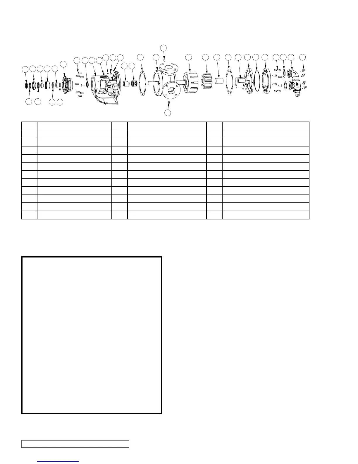
ITEM NAME OF PART ITEM NAME OF PART ITEM NAME OF PART
1 Locknut 19 Mechanical Seal 38 Idler Bushing
2 Lockwasher 25 Bracket Bushing 39 Idler Pin
3 End Cap 26 Pressure Relief Fitting for Bracket 40 Head and Idler Pin Assembly
4 Bearing Spacer Collar (Outer) 27 Bracket 41 Gasket for Jacket Head Plate (4224B)
5 Lip Seal 28 Capscrew for Bracket 42 Jacket Head Plate (4224B)
6 Ball Bearing 29 Bracket Gasket 43 Capscrew for Head
7 Bearing Housing 30 Pipe Plug 45 Relief Valve Gasket
8 Bearing Spacer Collar (Inner) 31 Casing (Tapped or Flanged) 46 Capscrew for Relief Valve
11 Ring, Half Round (Not G, H, HL) 35 Head Gasket 47 Internal Relief Valve
12 Grease Fitting 36 Rotor and Shaft
18 Lip Seal 37 Idler
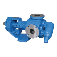
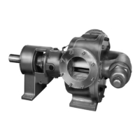
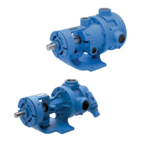
REPAIR: MODELS G, H, HL, AK, K, KK, L, LQ AND LL
BEHIND THE ROTOR COMPONENT MECHANICAL SEAL PUMPS
FIGURE 3 - EXPLODED VIEW SERIES 4124B MODELS
1. Mark head and casing before disassembly to insure
proper reassembly. The idler pin, which is offset in pump
head, is positioned toward and equal distance between
port connections to allow for proper flow of liquid through
the pump.
Remove head from pump. Do not allow idler to fall from
idler pin. Tilt top of head back when removing to prevent
this. Avoid damaging head gasket. If pump is furnished
with pressure relief valve, it need not be removed from
head or disassembled at this point. Refer to Pressure
Relief Valve Instructions, page 7.
If pump has jacketed head plate, it will separate from
head when it is removed. The gasket between head and
jacket head plate must be totally removed. Use new
gasket when assembling pump.
2. Remove idler and bushing assembly.
3. Insert length of hardwood or brass through port opening
between rotor teeth to keep shaft from turning. Bend up
tang of lockwasher and with a spanner wrench, remove
locknut and lockwasher from shaft. Note: G size uses
sealed bearings and does not have a lock washer, lip
seals or half-round rings.
4. Loosen two setscrews in the face of the bearing housing
and remove the bearing housing assembly from the
bracket. Refer to Figure 4.
5. Remove pair of half round rings under the inner spacer
collar from the shaft. There are no half round rings on the
G, H and HL size pumps.
DISASSEMBLY
DANGER !
Before opening any Viking pump liquid chamber
(pumping chamber, reservoir, relief valve
adjusting cap fitting, etc.) Be sure:
1. That any pressure in the chamber has been
completely vented through the suction or
discharge lines or other appropriate openings
or connections.
2. That the driving means (motor, turbine,
engine, etc.) has been “locked out” or made
non-operational so that it cannot be started
while work is being done on pump.
3. That you know what liquid the pump has been
handling and the precautions necessary to
safely handle the liquid. Obtain a material
safety data sheet (MSDS) for the liquid to be
sure these precautions are understood.
Failure to follow above listed precautionary
measures may result in serious injury or death.
1
2
3
5
4 6
5
8
11
7
28 18
27
12
26
30 12
25
19
29 3631 37 38 35 4039 41 42 43 45 47 46
30
30