SECTION TSM 628 ISSUE A PAGE 6 OF 8
12. Install the lip seal (lip toward end of shaft) in the bearing
housing and turn the bearing housing into the bracket.
13. Pack the ball bearing with grease, place on the shaft and
push or drive into place in housing.
14. Install the lip seal (with lip toward end of shaft) and
bearing spacer collar in the outer end cap and turn the
end cap into the bearing housing until tight against the
bearing. Lock in place with two set screws in the flange
of the bearing housing. Note: G size has no lip seal.
15. Put lockwasher and locknut on shaft. Insert length of
hardwood or brass through port opening between rotor
teeth to keep shaft from turning. Tighten locknut to
20-30 ft.–lbs. torque (G), 50-70 ft.–lbs. torque (H, HL) or
100-130 ft.–lbs. torque (AK, K, KK, L, LQ, LL). Bend one
tang of lockwasher into slot of locknut. If tang does not
line up with slot, tighten locknut until it does. Failure to
tighten locknut or engage lockwasher tang could result
in early bearing failure and cause damage to pump.
Note: G size has no lockwasher.
Remove length of hardwood or brass from port opening.
When installing carbon graphite bushings, extreme care
must be taken to prevent breaking. Carbon graphite is a
brittle material and easily cracked. If cracked, the bushing will
quickly disintegrate. Using a lubricant and adding a chamfer
on the bushing and the mating part will help in installation.
The additional precautions listed below must be followed for
proper installation.
1. A press must be used for installation.
2. Be certain bushing is started straight.
3. Do not stop pressing operation until bushing is in proper
position. Starting and stopping will result in a cracked
bushing.
4. Check bushing for cracks after installation.
Carbon graphite bushings with extra interference fits are
frequently furnished for high temperature operation. These
bushings must be installed by a shrink fit.
1. Heat bracket for idler to 750ºF.
2. Install cool bushing with a press.
3. If facilities are not available to reach 750ºF. temperature,
it is possible to install with 450ºF. temperature; however
the lower the temperature the greater the possibility of
cracking the bushing.
Consult factory with specific questions on high temperature
applications. Refer to Engineering Service Bulletin ESB-3.
INSTALLATION OF CARBON
GRAPHITE BUSHINGS
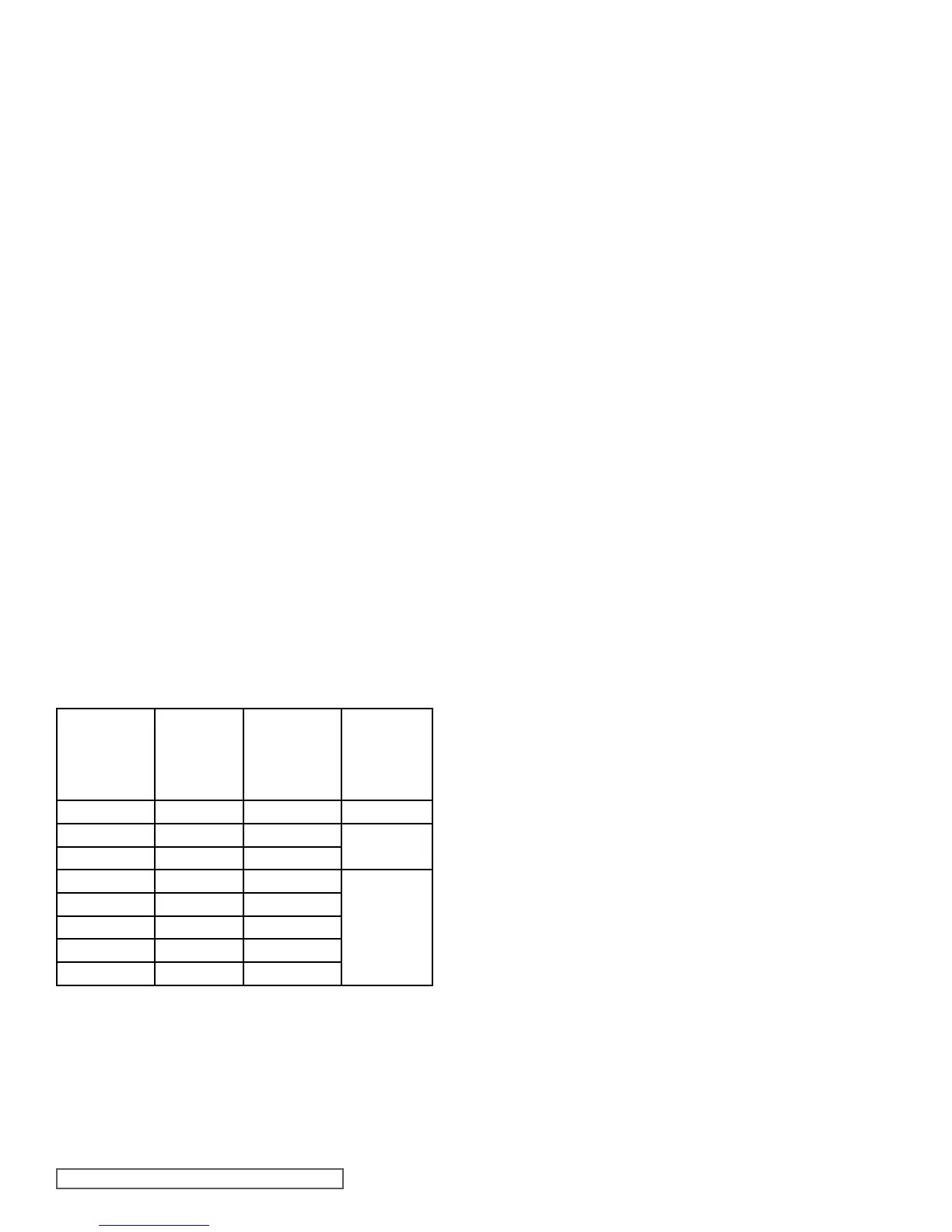
THRUST BEARING ADJUSTMENT
SIZE G, H, HL, AK, K, KK, L, LQ,
& LL PUMPS
PUMP
STANDARD
END
CLEARANCE
TURN
BEARING
HOUSING
CCW LENGTH
ON OD (INCH)
ADDITIONAL
LENGTH ON
OD BEARING
HOUSE FOR
0.001" END
CLEARANCE
G 4124B 0.003" 0.60" 0.20”
H & HL 4124B 0.003" 0.75"
0.22”
H & HL 4224B 0.007" 1.5"
AK4124B 0.005" 1.25"
0.25”
K & KK 4124B 0.005" 1.25"
K & KK 4224B 0.010" 2.5"
L , LQ, LL 4124B 0.005" 1.25"
L, LQ, LL 4224B 0.010" 2.5"
TABLE 1
1. Loosen the two set screws in the outer face of the
bearing housing and turn this thrust bearing assembly
clockwise until it can no longer be turned by hand. Back
off counter-clockwise until the rotor shaft can be turned
by hand with a slight noticeable drag.
2. For standard end clearance, back off the thrust bearing
assembly the required length measured on the outside
diameter of the bearing housing. See Table 1.
3. Tighten the two self-locking type “Allen” set screws, in
the outboard face of the bearing housing, with equal
force against the bracket. Your pump is now set with
standard end clearances and locked.
NOTE: Be sure the shaft can rotate freely. If not, back off
additional length on outside diameter and check again.
4. High viscosity liquids required additional end
clearances. The amount of extra end clearance depends
on the viscosity of the liquid pumped. For specific
recommendations, consult your Viking Pump distributor.
Before putting pump back into service, add grease to the
bracket grease fitting until it comes out of the relief fitting on the
opposite side of the bracket (use petroleum jelly, petrolatum or
other similar low melting point lubricant). Regrease the bearing
housing until grease comes out of the shaft end lip seal (use
multi-purpose grease NLGI #2).
RELUBRICATION