SECTION TSM 628 ISSUE A PAGE 5 OF 8
6. Carefully remove rotor and shaft to avoid damaging
bracket bushing. If damaged or worn, remove bushing.
7. Remove bracket lip seal (Item 18).
8. Loosen two radial setscrews in flange of bearing housing
and with a spanner wrench remove the outer end cap
with lip seal and outer bearing spacer collar. Note: G
size uses sealed bearings and does not have a lock
washer, lip seals or half-round rings.
9. Remove the double row ball bearing, lip seal and inner
bearing spacer collar from the bearing housing. Note:
G size uses sealed bearings and does not have a lock
washer, lip seals or half-round rings.
10. Remove the rotary member of the mechanical seal from
the rotor shaft. Remove the seal seat from the bracket.
11. Clean all parts thoroughly and examine for wear and
damage. Check lip seals, ball bearing, bushings, and
idler pin and replace if necessary. Check all other parts
for nicks, burrs, excessive wear and replace if necessary.
Wash bearings in clean solvent. Blow out bearings with
compressed air. Do not allow bearings to spin; turn them
slowly by hand. Spinning bearings will damage race and
balls. Make sure bearings are clean, then lubricate with
light oil and check for roughness. Roughness can be
determined by turning outer race by hand.
Note: G size uses sealed bearings
12. Casing can be checked for wear or damage while
mounted on bracket.
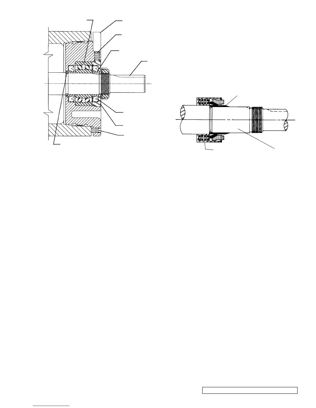
HALF ROUND
RINGS
FIGURE 4
END CAP
LIP SEAL
SPACER COLLAR
SETSCREW
SHAFT
SETSCREW
BEARING HOUSING
BALL BEARING
1. Install bracket bushing. If bracket bushing has a
lubrication groove, install bushing with groove at 6.00
o’clock position in bracket. If carbon graphite, Refer to
Installation of Carbon Graphite Bushings, page 6.
Make sure slots in the face of the bushing are towards
rotor end of the bracket.
ASSEMBLY
2. Clean rotor shaft and seal housing bore. Make sure they
are free of dirt, grit and scratches. Gently radius leading
edge of shaft diameter over which seal is to be placed.
Never touch mechanical seal faces with anything except
clean hands or clean cloth. Minute particles can scratch
the seal faces and cause leakage.
3. Place tapered installation sleeve on the shaft. Coat
tapered sleeve and inside of the rotary member
with a generous quantity of light oil. Grease is not
recommended. Start rotary member on shaft and over
tapered sleeve. Refer to Figure 5.
FIGURE 5
TAPERED INSTALLATION SLEEVE
SHAFT
MECHANICAL SEAL
ROTARY MEMBER
4. Move rotary member all the way on the rotor shaft until
it is against the rotor hub. If the seal uses setscrews to
secure the seal to the shaft, tighten the setscrews once
the seal is in place. Some PTFE seals are equipped with
holding clips which compress the seal springs. Remove
holding clips to release springs after seal is installed on
shaft.
5. Lubricate outer diameter of seal seat gasket with oil.
Press seal seat into bore until back, unlapped face
bottoms in bore. Make sure the seat anti-rotation pins
are aligned with slots in the bracket bushing.
6. Coat rotor shaft and face of mechanical seal with light
oil. Start end of shaft in bracket bushing turning from
right to left, slowly pushing rotor in casing.
7. Coat idler pin with light oil and place idler and bushing
on idler pin in head. If replacing with carbon graphite
bushing, Refer to installation of Carbon Graphite
Bushings, page 6.
8. Using a .010 to .015 inch head gasket, install head and
idler assembly on pump. Pump head and casing were
marked before disassembly to insure proper reassembly.
If not, be sure idler pin, which is offset in pump head,
is positioned toward the equal distance between port
connections to allow for proper flow of liquid through
pump. If pump is equipped with jacketed headplate,
install at this time along with new gasket.
9. Tighten head capscrews evenly.
10. Install bracket lip seal (Item 18, lips toward head end).
11. Slide inner spacer collar over shaft with recessed end
facing rotor. G, H and HL size bearing spacer collars are
not recessed.
Place pair of half round rings on shaft and slide inner
bearing spacer collar over half round rings to lock them
in place. There is no pair of half round rings on the G, H
and HL size pumps.