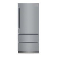
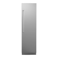
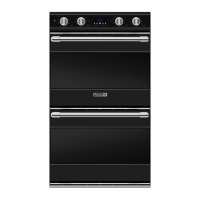
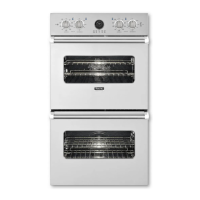
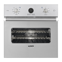
This document is an installation guide for the Viking 7 Series Integrated Refrigerator/Freezer, covering models VBI7360/CVBI7360, FBI7360/CFBI7360, MVBI7360/CMVBI7360, and MFBI7360/CMFBI7360. It provides comprehensive instructions for the proper installation, operation, and maintenance of the appliance, emphasizing safety and compliance with electrical and plumbing codes.
The guide begins with crucial safety warnings, highlighting the importance of reading and following all instructions to prevent serious injury or death. It uses safety alert symbols and keywords like "DANGER" and "WARNING" to draw attention to potential hazards, such as electrical shock and tip-over risks. The appliance is top-heavy and can tip easily if not properly installed, necessitating the use of an anti-tip bracket and requiring two or more people for moving and installation. Installers are advised to wear gloves and eye protection when handling the unit.
For installation, the document outlines several area requirements. The unit must fit through doorways and corners, and the floor must be capable of supporting the appliance's weight plus food (approximately 1200 pounds or 540 kg). The floor underneath the refrigerator should be level with the surrounding finished floor. It's important to remove any obstructions from the rear or side walls of the cutout. The guide explicitly states not to install the refrigeration unit near a heat source or in a location where temperatures drop below 60°F (16°C).
Electrical requirements specify a 115-volt, 60-Hz, 15-amp, fused electrical supply on a dedicated circuit. The appliance is equipped with a 3-prong grounding plug, which must be connected to a mating 3-prong, grounding-type wall receptacle. The use of extension cords or ungrounded (two-prong) adapters is prohibited. If a Ground Fault Interrupter (GFI) is required by local codes, it must be of the receptacle type (not breaker or portable), used with permanent wiring, on a dedicated circuit, connected to a standard breaker, rated for Class A (5 mA +/- 1 mA trip current), and in good condition, protected from moisture. Viking Range, LLC will not warranty problems resulting from improperly installed or non-compliant GFI outlets.
Water supply requirements are detailed for units with ice makers. Only 1/4" (6 mm) copper tubing should be used for the water line, and it should not be installed in areas where temperatures drop below 35°F (1.7°C) to prevent freezing. Before connecting the copper tubing to the unit, it must be flushed with at least 2 quarts (1.9 L) of water to remove any particles. The guide warns against connecting to a microbiologically unsafe or unknown quality potable water supply without adequate disinfection. It also advises against using plastic water lines from household plumbing and self-piercing saddle valves, as the latter can restrict water flow to the ice maker. A separate shut-off valve should be installed in an easily accessible location, not behind the unit. For reverse osmosis systems, water pressure must remain within 20-120 psi for non-dispenser units and 35-120 psi for dispenser units.
Unpacking instructions include removing top and bottom straps, the top cap, and cutting the carton rear. Installers are advised to save cardboard shipping material to protect the floor and to remove the anti-tip bracket from the shipping pallet. The flush mount side trim is taped to the handle side of the unit and should be removed.
Moving the unit requires slipping an appliance dolly between the unit and the skid after removing four bolts from the shipping brackets. Excess packaging should be used to protect decorative trim, and leveling legs should be adjusted to 0" (up) before moving.
The guide provides detailed instructions for installing custom front panels. Each panel overlay must be dry, solid, straight, and one-piece. Maximum panel weights are specified: 39 lbs (17.6 kg) for the refrigerator door, 10 lbs (4.5 kg) for the top freezer drawer, and 13 lbs (5.9 kg) for the bottom freezer drawer. To access mounting holes, panel trim on both sides of all three doors must be unsnapped.
Water line installation involves inserting copper tubing through an indicated hole in the machine compartment, coiling it in a vertical loop, and connecting it to the water valve using a nut and ferrule. The bottom freezer drawer and toe kick must be removed to access the connection area. After connection, the water supply should be turned on to check for leaks.
Leveling the unit is a critical step, performed from the front after the unit is in position. A 5/16" hex drive is used to turn leveling legs clockwise to raise or counterclockwise to lower. The unit must be leveled to the floor, not surrounding cabinetry, to ensure proper operation, including door closing.
Kickplate installation involves placing the kickplate on the lower front, aligning adjustment screws in the slots, letting it drop to the floor, and then tightening the screws.
Flush mount side trim installation requires fastening the unit to the cabinetry using provided flat wood screws, taking care not to scratch the frame. A 3" Phillips driver is recommended. The flush mount side trim is then snapped onto the side opposite the door swing.
The door stop adjustment section explains how to change the door opening angle from the factory-set 90° to 105°. This involves locating the door stop on top of the door hinge, removing two screws, rotating the door stop 180° so the shorter end faces away from the door, and then replacing the door stop and screws.
A performance checklist is included to verify proper installation, covering aspects like cabinet size, electrical and water supply, anti-tip device, leveling, water connection, icemaker fill tube, icemaker bail arm, dispenser operation, drain pan, kickplate, and removal of internal packaging and labels.
The guide also covers verify operations and control panels, including how to initiate the display, enter/exit Sabbath Mode, and enter/exit Showroom Mode. The power on/off switch is located behind the access panel and is used to turn the power off for cleaning or servicing.
Finally, the document includes a section for service and registration, advising users to contact an authorized service agency if needed. It requests recording model number, serial number, date purchased, dealer's name, and address for future reference. It also emphasizes using only authorized parts for repairs to ensure warranty protection. The water filter system specifications and performance data sheet are provided, detailing the reduction of various contaminants and operating specifications for the water filter.