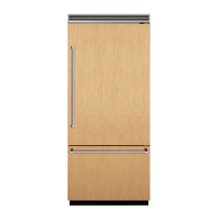
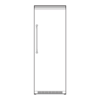
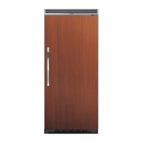
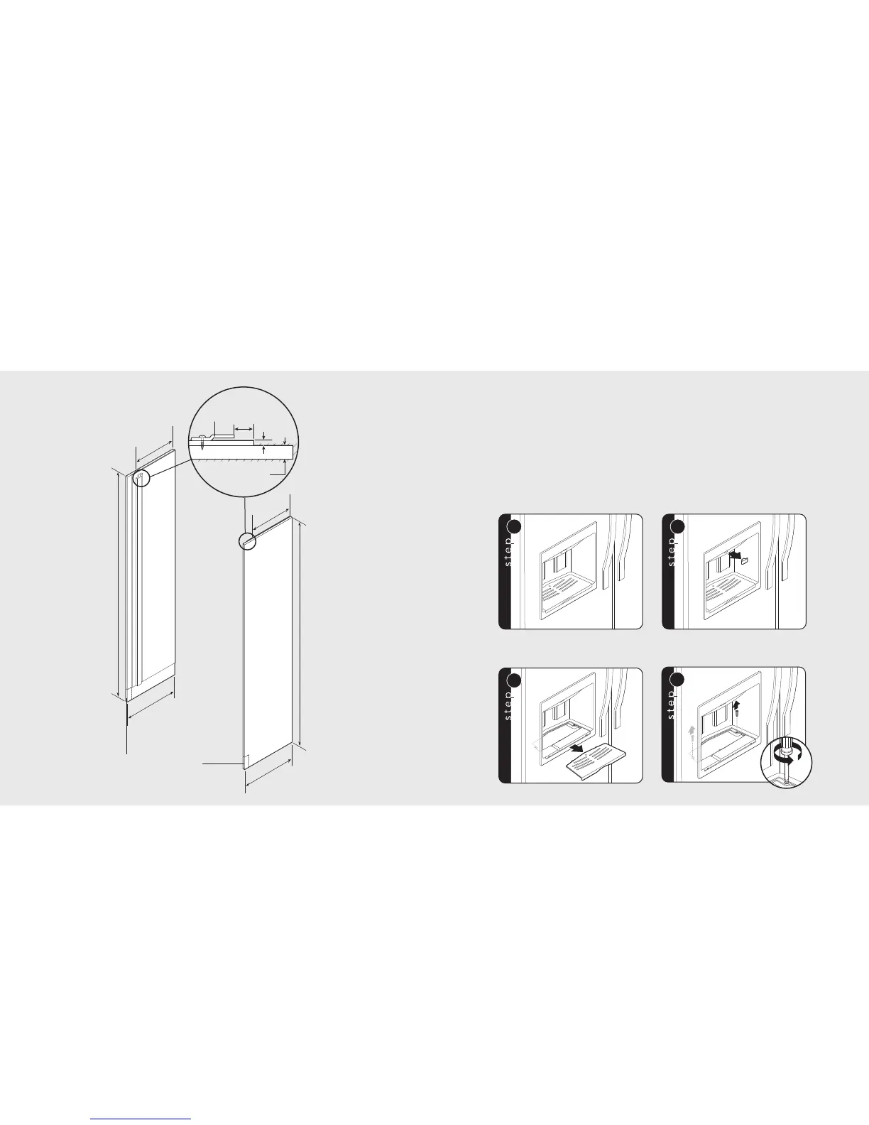
Custom Side Panel Dimensions
47
46
*Note: Depending on how high leveling feet are raised, and cabinet enclosure height.
Custom Panel General Information
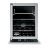
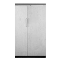
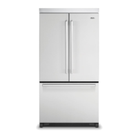
Custom finishing options
• All installations must allow for the refrigerator
and freezer door to open a minimum of 90˚.
• For side wall or corner installation, allow for a
standard 3” (7.6 cm) cabinet filler to assure
door(s) opens 90˚.
Note: If a custom handle is used, a wider filler
may be necessary.
• Panel thickness must not exceed 1” (2.5 cm)
on hinge side. Thicker panels will interfere with
door swing and clearance.
• A 1/4” wood filler or insulation filler must be
used between the door and 3/4” wood panel
to prevent condensation from forming.
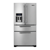
Ice and Water Dispenser Bezel Removal (if required)
Note: Designer model shown.
Remove packaging material surrounding bezel.
Grasping the sliding lever, pull away from bezel.
Remove spill tray from lower part
of bezel exposing 2 screws.
Remove screws.
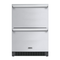
Note: Adding 3/4”
(1.9 cm) side panels adds
an additional 3/4” (1.9 cm)
to the overall width of
the product for each
side panel used.
Note: Requires side panel
hardware kit (SPHKDS).