26
© 2012 Viking Preferred Service
Service Diagnostics and Procedures
Component Testing
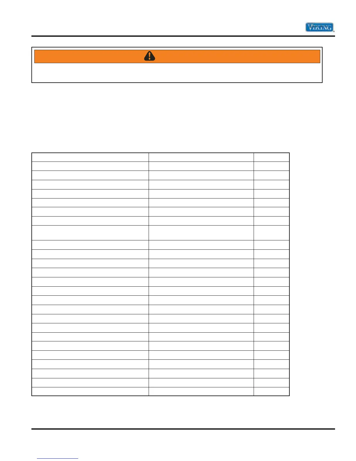
The unit has a main control board, a secondary control board and UI (dispenser) board that control functions
of the respective refrigerator/freezer compartment. Components can be diagnosed via these boards. With the
board accessed (refer to main and secondary control boards access procedure, page 52 and control board
access procedure, page 32), the following can be measured:
Component Testing–Control Board
Component Test Point Reading
Defrost Terminator and Defrost Heater P3-3 (Brown) – P1-2 (White) 55.7K Ω
Refrigerator Light Switch P1-1 (Red) – P4-3 (Black) 1M Ω
Freezer Light and NC Freezer Light Switch P1-1 (Red) – P5-1 (Red/Orange) 24.7 Ω
Defrost Terminator P3-3 (Brown) – P5-6 (Orange) 55.7K Ω
Damper Motor P5-5 (Blue/Red) – P1-2 (White) 1.4M Ω
Evaporator Fan P3-1 (Black/Yellow) – P1-2 (White) 1M Ω
Common Damper Motor P3-2 (Yellow/Red) – P1-2 (White) –
Evaporator Fan and Defrost Heater P3-1 (Black/Yellow) – P3-3 (Brown) Defrost
Thermostat closed
55.8K Ω
Ice Maker P1-1 (Red) – P1-2 (White) 100M Ω
Water Dispenser Switch P6-3 (Yellow) – P6-8(Yellow) 20K Ω
Normally Closed Motorized Damper P5-5 (Blue/Red) – P1-2 (White) ∞ Ω
Fresh Food Thermistor P6-6 (White/Blue) – P6-1 (White/Orange) 2.38K Ω
Freezer Thermistor P6-7 (White/Yellow) – P6-1 (White/Orange) 2.38K Ω
Ambient Thermistor P6-9 (White/Violet) – P6-1 (White/Orange) 2.38K Ω
Freezer Thermistor and Ambient Thermistor P6-6 (White/Blue) – P6-9 (White/Violet) 4.5K Ω
Condenser Fan Motor and PTC Overload Relay P1-4 (Blue) – P1-2 (White) 3.9 Ω
Condenser Fan Motor and PTC Overload Relay P1-4 (Blue) – P1-2 (White) 3.9 Ω
Common Freezer Light Switch P5-1 (Red/Orange) – P1-1 (Red) 3.2M Ω
Power Cord (Neutral) P1-2 (White) –
Mullion Heater P7-9 (Blue/White) – P7-10 (Red/Black) 24.5 Ω
Mullion Heater P7-9 (Blue/White) – P7-10 (Red/Black) 24.5 Ω
+14 VDC Display PC Board P10-1 (Red/Black) – P10-2 (Black/Green) 5.6K Ω
Wide Display PC Board P8-2 (Yellow/Black) – P8-3 (Black/Green) –
Dig Ground PC Board P8-3 (Black/Green) –
Compound Ground and Base Pan Ground Green/Yellow –
WARNING
To avoid risk of electrical shock, personal injury, or death, disconnect electrical power to unit using power
switch before servicing. After servicing, reconnect power using power switch.