27
© 2012 Viking Preferred Service
Service Diagnostics and Procedures
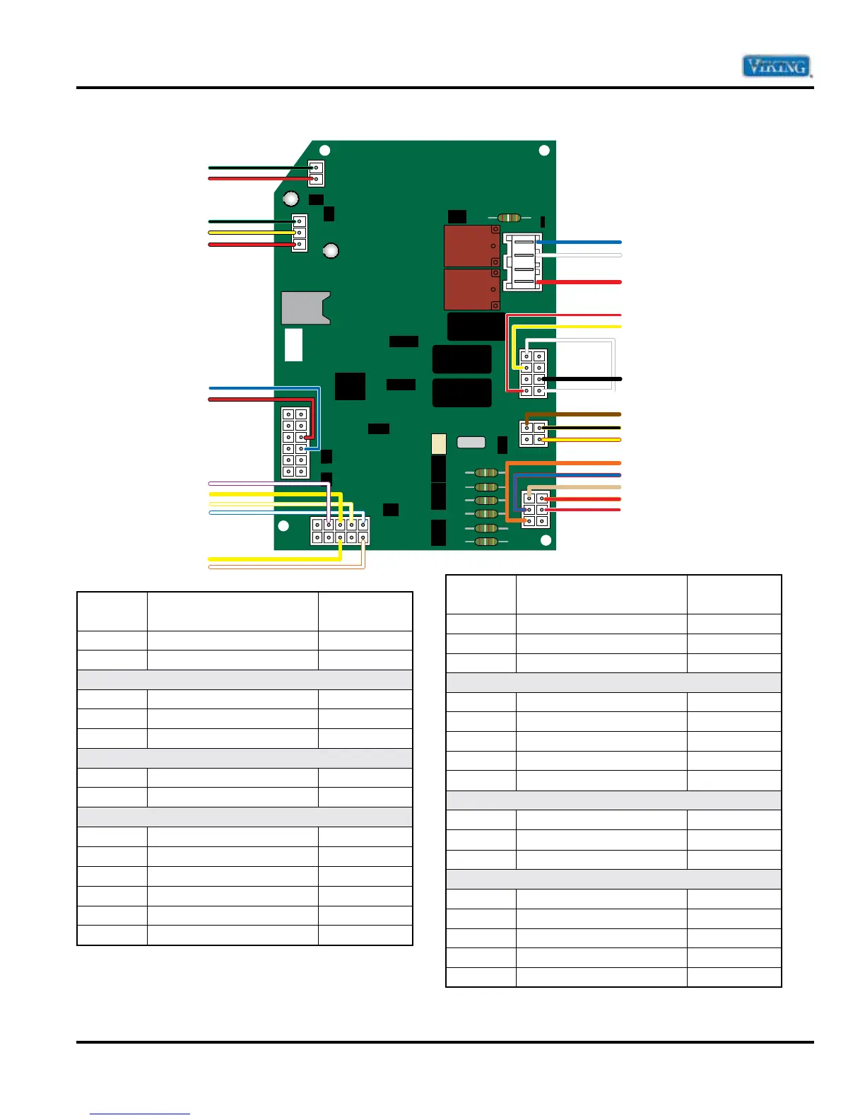
Main Control Board Wiring Connections
Pin
Number Description Wire Color
P10-2 Dig Ground Black/Green
P10-1 +14VDC Red/Black
P8-3 Dig Ground Black/Green
P8-2 Wide PCB Yellow/Black
P8-1 +14VDC Red/Black
P7-9 Trio Heater Blue/White
P7-10 +14VDC Red/Black
P6-9 Ambient Thermister White/Violet
P6-8 Dispenser Yellow
P6-7 Freezer Thermister White/Yellow
P6-6 Fresh Food Thermister White/Blue
P6-3 Dispenser Yellow
P6-1 Thermister Ground White/Orange
Pin
Number Description Wire Color
P1-4 Compressor Blue
P1-3 Neutral White
P1-1 L1 Red
P4-8 L1 Red/White
P4-6 Dispenser Valve Yellow/White
P4-5 Neutral White
P4-3 Neutral Black
P4-4 Neutral White
P3-3 Defrost Thermostat Brown
P3-1 Evaporator Fan Black/Yellow
P3-2 Damper Motor Yellow/Red
P5-6 Defrost Heater Orange
P5-2 Damper NO Blue/Red
P5-4 Ice Maker Valve Tan
P5-1 FC Lite Red/Orange
P5-2 RC Lite Red/White
P8-3
P8-2
P8-1
P1-4
P1-3
P1-1
P4-8
P4-6
P4-5
P4-3
P4-4
P3-3
P3-1
P3-2
P10-2
P10-1
P7-9
P7-10
P6-9
P6-8
P6-7
P6-6
P6-3
P6-1
P5-6
P5-5
P5-4
P5-1
P5-2
10
1