27
Component Testing
Compressor Description Test Procedure
Refrigerant gas is pulled through 1. Separate evaporate from rest of refrigeration system and
suction line by compressor to pressurize evaporator up to a maximum of 235 PSI with
complete the refrigerant cycle. a refrigerant and dry nitrogen combination.
2. Recheck for leaks.
Heater, Applied to back of ice and water Check resistance across heater.
cavity cavity to help prevent conden-
sation from forming on face of If heater is faulty, use spare heater foamed in place at factory.
cavity. Wire in series with hot
side of line through auger motor
interlock switch.
Heater, See “Electronic Function Check resistance across heater.
evaporator Description, Adaptive Defrost
(defrost) Circuitry. To check defrost system:
1. Thermocouple defrost thermostat and plug refrigerator into
wattmeter.
2. Force into defrost mode (see section on electronic testing)
Wattmeter should read specified watts (according to Technical
Data Sheet) ±5 F; thermostat should interrupt power to heater
Heater mullion For service use only to reduce
condensation on center mullion.
Heater formed in place. Not To connect mullion heater to power:
powered from the factory. 1. Disconnect power to unit using power switch.
2. Remove ice grille.
3. Remove bracket holding condenser evaporation fan and water valve.
4. Locate water valve wiring harness.
5. Carefully slit wiring harness vinyl sleeve to expose one black and
one white lead with bullet terminals inside harness sleeve.
6. Connect to heater leads at left side of cabinet.
7. Wrap vinyl sleeve with electrical tape to close slit.
Icemaker See “icemaker” section for
service information.
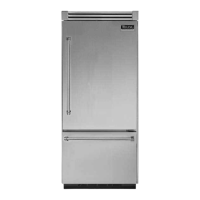
Motor Condenser fan moves cooling Check resistance across motor windings
Condenser
air across condenser coil and
compressor body.
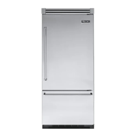
Motor Evaporator motor moves air 1. Disconnect power to unit.
Evaporator across evaporator coil. 2. Disconnect fan motor leads.
3. Check resistance from ground connection solder. Trace to motor
frame must not exceed .05 ohms.
4. Check for voltage at connection to motor.