30
Component Testing
Compressor Description Test Procedure
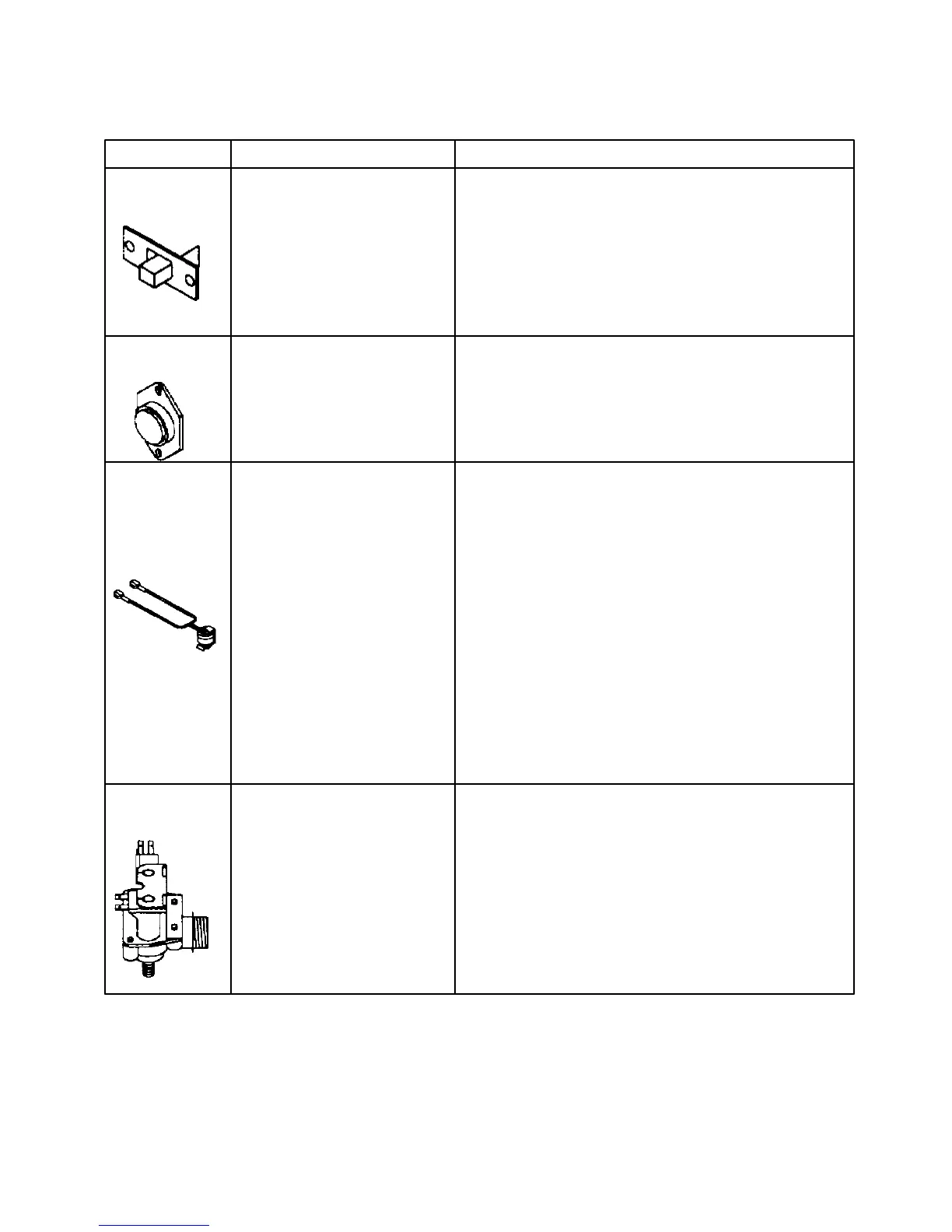
Switch, showroom ON position completes circuit to Check resistance at test points.
SPDT lights and display only Showroom operation –E3 at high voltage board to pin
3 (blue/white wire) at high voltage wire harness.
OFF position completers circuit
for normal operation. Unit run—E9 at high voltage board to pin 3
(blue/white wire) at high voltage wire harness.
Unit shipped with switch in OFF
position.
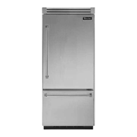
Thermistor Senses temperature within Check resistance across terminals. See Technical Date
Refrigerator and freezer. Sheet for bell curve resistance chart at given temperature.
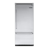
Thermostat Thermostat is in a series circuit With power off and evaporator coil below freezing
with high voltage board and thermostat should check continuous when checked
defrost heater. with ohmmeter. See “Heater, evaporator (defrost)”
section for additional tests.
Controls the circuit through
defrost terminator to defrost
heater. Opens and breaks circuit
when thermostat senses present
high voltage.
After defrost thermostat opens
thermostat remains open until
end of defrost cycle and
refrigerator starts cooling again.
When defrost thermostat senses
a preset low temperature and
closes.
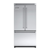
Valve, water controls water flow to the ice Check resistance across coil windings. See Technical
Maker. Data Sheet for valves for model being serviced.