11
Safety and Technical Manual
Rev: 2
Form No. F_020521
VSF303 Flame Detector
This document is strictly private and confidential, reproduction without Viking Corporation approval is prohibited. © 2021 The Viking Group Inc.
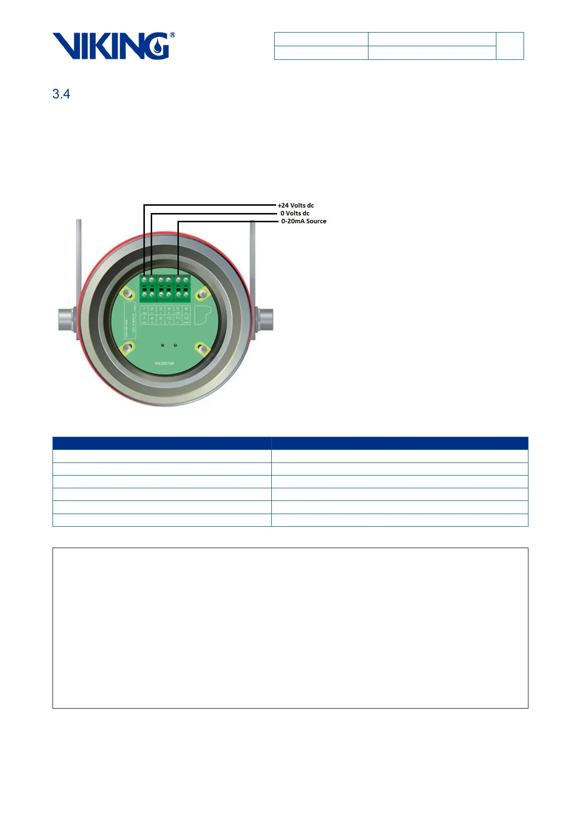
0-20mA Output
The following wiring connection diagram shows correct wiring of the detector when a 0-20mA output
is required.
Figure 5: 3 Wire Termination
Factory Fixed Values
Note 1 - The tolerance on the above outputs is +/- 0.3mA current with a maximum loop resistance
of 500 ohms.
Note 2 – Additional 0-20mA values are configurable and must be specified when ordering if
required. The optical fault signal may be configured at 2mA as opposed to 1.5mA and the alarm
signal may be increased to 20mA.
Note 3 - The VSF303 can be factory-configured with an Aux alarm delay (20mA) of between 0
and 10 seconds in 1 second steps over and above the normal response times of the 18mA alarm
signal. If the Aux alarm signal is delayed, the 18mA alarm signal will precede the 20mA signal
giving the normal response times as tested by Factory Mutual to FM3260. If the 20mA alarm
signal is delayed, it is considered an Aux alarm level.
Note 4 – The 0-20mA signal has HART ® 7 protocol superimposed on top of it to give access to
more diagnostic information. See HART ® 7 Technical Note.