12
Safety and Technical Manual
Rev: 2
Form No. F_020521
VSF303 Flame Detector
This document is strictly private and confidential, reproduction without Viking Corporation approval is prohibited. © 2021 The Viking Group Inc.
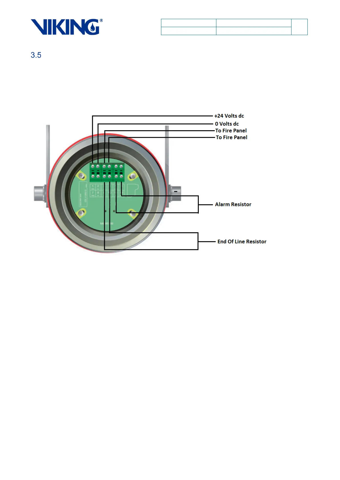
Relay Output
The following wiring connection diagrams shows wiring the detector when a relay output is required.
Reversal of polarity across terminals 1 & 2 enables Viking RS485 communication on terminals 3 &
4. This communication protocol, when used with Viking applications, allows configuration changes
to the detector.
Figure 6: Relay Configuration Termination
NOTE: EOL and alarm resistors values are defined by the client and the control system/fire
panel which the detectors are being integrated into.