39
This table shows typical connections. OEMs may have a dierent connection scheme.
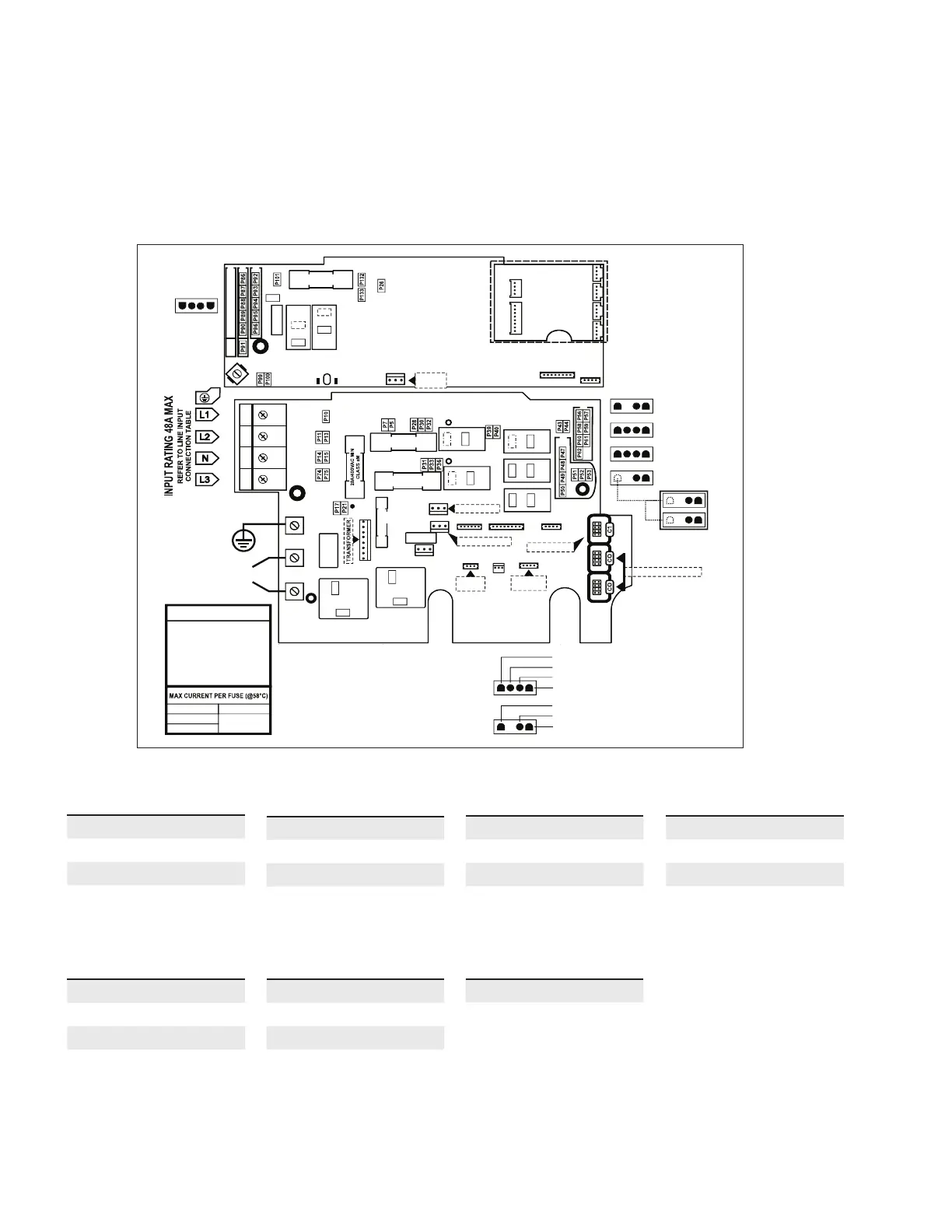
Connections - 0611-221037-566
Connecting high voltage accessories: European model in.yt
For the connection to the 0.25 inch (6mm) terminals, the high voltage accessories must be provided with female quick
connect terminals, straight and non-insulated for all types of connections, including the ground. Only 230 V accessories
may be connected to the corresponding terminals of the printed circuit of the in.yt. Refer to the following tables for
correct connections. Note that all female terminals must be correctly and completely seated on the printed circuit
terminals for proper current ratings.
Pump 1 (A3)
Voltage 230 V
Green / Earth G
Black / low speed K2
Red / high speed K1
White / neutral N
Direct (A4)
Voltage 230 V
Green / Earth G
Black / live K26
White / neutral N
Light (C2)
Voltage 230 V
Green / Earth G
Red / live K22
White / neutral N
Pump 2 (C2)
Voltage 230 V
Green / Earth G
Black / low speed K23
Red / high speed K22
White / neutral N
Circulation pump (A2)
Voltage 230 V
Green / Earth G
Red / live K6
White / neutral N
Ozonator (A1)
Voltage 230 V
Green / Earth G
Black / live K4
White / neutral N
Light (12 V AC, 1A Max.)
Always on P34
Relay P35
Light (12 V AC, 1A Max.)
Always on P34
Relay P35
A3
A4
A1
A2
C2
- USE ONLY SAME TYPE
AND RATING OF FUSE
- UTILISER SEULEMENT
LE MÊME TYPE DE
FUSIBLE, DU MÊME
COURANT NOMINAL
WARNING
OPTIONAL
PP1 SPLITTER
F2 : 20A MAX
F3 : 20A MAX
F1 : 20A MAX
F21 : 20A MAX
HEATER
CONNEXION
HEATER
GROUND
HIGH SPEED (RED)
LOW SPEED (BLACK)
COMMON (WHITE)
GROUND (GREEN)
LIVE (BLACK)
COMMON (WHITE)
GROUND (GREEN)
P4
P3
P5
P6
P7
P8
P113
P112
P108
F21
20A/400VAC MIN
CLASS aM
K22
P
YG
P97
K23
P
P34
K21
P98
X
P116
REL AY
SUPPLY
K1
K3
K2
K4
K6
K5
K9
K10
P37
P34
P6
P2
P3
P4
P8
P29
P41
P45
P35
F2
20A/400VAC MIN
CLASS aM
20A/400VAC MIN
CLASS aM
F3
F1
F4
1
2
3
4
250mA/250VAC
3AG SLOW-BLO
P
P
P
P
P
C
C
P22
P76
K8
P
P
COMMUNICATION LINKS
COMMUNICATION LINKS
MAIN KEYPAD
G
N
P55
P19
LIGHT, SWITCHED
P83
LIGHT, DIRECT
P66
P38
H L & TEMP.
PROBE
P42
IN.FLO
SENSOR
IMPORTANT: See electrical connection and jumper set up on page 41 for 1, 2, 3 phase connections.
NOTE: e A9L model can be operated with various electrical configurations. However, certain set ups may result in limited operation.
For full functionality, configurations with 3x16A three-phase circuits, 2x20A two-phase circuits, or one 40A single-phase circuit are required.
Alternative configurations with currents other than those recommended will compromise spa functionality (e.g. lower heating and
water flow performance).
This table shows typical connections. OEMs may have a dierent connection scheme.
Connections - 0611-221037-566
Connecting high voltage accessories: European model in.yt
For the connection to the 0.25 inch (6mm) terminals, the high voltage accessories must be provided with female quick
connect terminals, straight and non-insulated for all types of connections, including the ground. Only 230 V accessories
may be connected to the corresponding terminals of the printed circuit of the in.yt. Refer to the following tables for
correct connections. Note that all female terminals must be correctly and completely seated on the printed circuit
terminals for proper current ratings.
Pump 1 (A3)
Voltage 230 V
Green / Earth G
Black / low speed K2
Red / high speed K1
White / neutral N
Direct (A4)
Voltage 230 V
Green / Earth G
Black / live K26
White / neutral N
Light (C2)
Voltage 230 V
Green / Earth G
Red / live K22
White / neutral N
Pump 2 (C2)
Voltage 230 V
Green / Earth G
Black / low speed K23
Red / high speed K22
White / neutral N
Circulation pump (A2)
Voltage 230 V
Green / Earth G
Red / live K6
White / neutral N
Ozonator (A1)
Voltage 230 V
Green / Earth G
Black / live K4
White / neutral N
Light (12 V AC, 1A Max.)
Always on P34
Relay P35
Light (12 V AC, 1A Max.)
Always on P34
Relay P35
A3
A4
A1
A2
C2
- USE ONLY SAME TYPE
AND RATING OF FUSE
- UTILISER SEULEMENT
LE MÊME TYPE DE
FUSIBLE, DU MÊME
COURANT NOMINAL
WARNING
OPTIONAL
PP1 SPLITTER
F2 : 20A MAX
F3 : 20A MAX
F1 : 20A MAX
F21 : 20A MAX
HEATER
CONNEXION
HEATER
GROUND
HIGH SPEED (RED)
LOW SPEED (BLACK)
COMMON (WHITE)
GROUND (GREEN)
LIVE (BLACK)
COMMON (WHITE)
GROUND (GREEN)
P4
P3
P5
P6
P7
P8
P113
P112
P108
F21
20A/400VAC MIN
CLASS aM
K22
P
YG
P97
K23
P
P34
K21
P98
X
P116
REL AY
SUPPLY
K1
K3
K2
K4
K6
K5
K9
K10
P37
P34
P6
P2
P3
P4
P8
P29
P41
P45
P35
F2
20A/400VAC MIN
CLASS aM
20A/400VAC MIN
CLASS aM
F3
F1
F4
1
2
3
4
250mA/250VAC
3AG SLOW-BLO
P
P
P
P
P
C
C
P22
P76
K8
P
P
COMMUNICATION LINKS
COMMUNICATION LINKS
MAIN KEYPAD
G
N
P55
P19
LIGHT, SWITCHED
P83
LIGHT, DIRECT
P66
P38
H L & TEMP.
PROBE
P42
IN.FLO
SENSOR
NEUTRAL
EARTH
NEUTRAL
EARTH
 Loading...