41
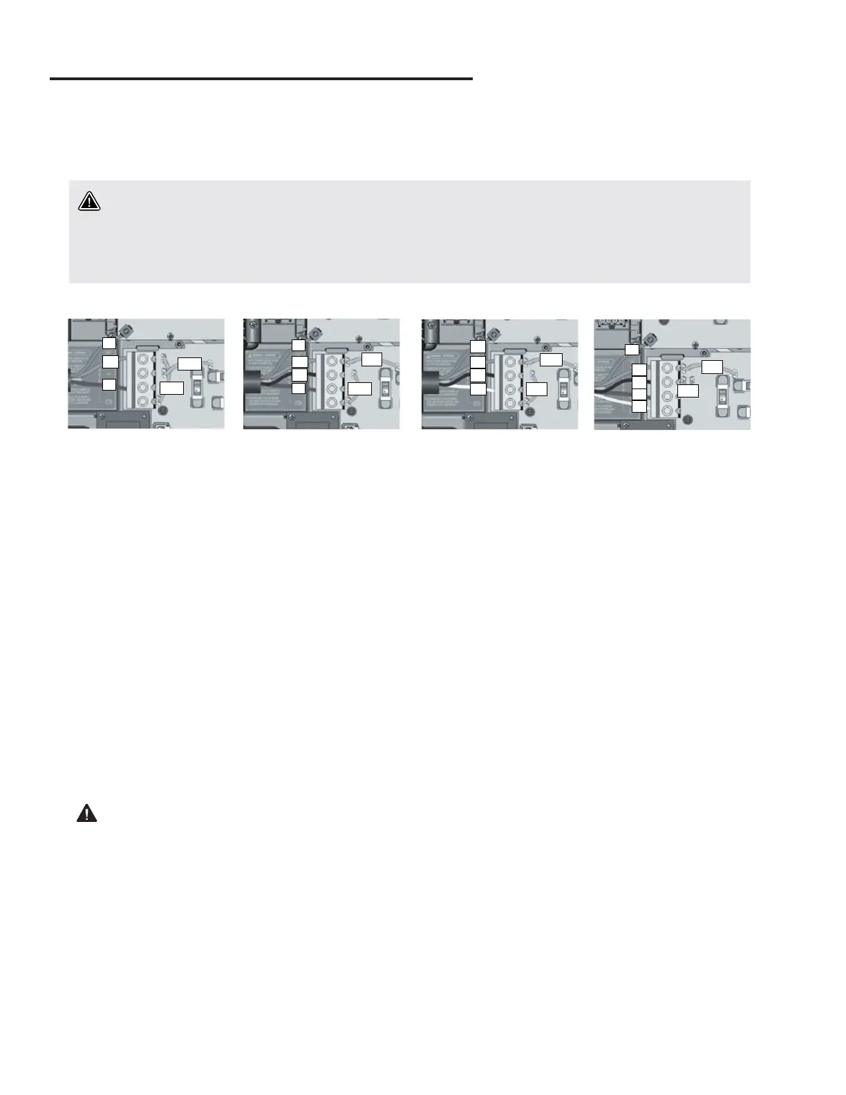
RCD WIRING DIAGRAMS
NOTE: On initial connection the installer is prompted for electrical configurations. e Low-Level setting is selected by the
installer. e Phase and Amperage is set automatically. Default settings should be confirmed by the installer to match the actual
phase and amperage at the spa’s installation location. In rare occasions it may be necessary to adjust the Phase and Amperage
setting to match the actual service available at the installation location using the Electrical Configuration instructions for your
spa’s specific control system.
Important note for the installer/dealer on the correct power settings
NOTE: e A9L model can be operated with various electrical configurations. However, certain set ups may result in limited operation.
For full functionality, configurations with 3x16A three-phase circuits, 2x20A two-phase circuits, or one 40A single-phase circuit are required.
Alternative configurations with currents other than those recommended will compromise spa functionality (e.g. lower heating and
water flow performance).
Electrical wiring: European model in.yt
PJ2
PJ1
N
L1
G
N
PJ2
PJ1
L1
L2
G
L3
PJ2
PJ1
L1
L2
G
N
PJ2
PJ1
L1
L2
L3
G
Refer to wiring diagram in the enclosure box lid for more information�
Warning
in�yt�ce models must always be connected to a circuit protected by a Residual-Current Device (RCD) having
a rated operating residual-current not exceeding 30 mA� Correct wiring of the electrical service box, RCD, and
pack terminal block is essential! Check your electrical code for local regulations� Only copper wire should be
used, never aluminum�
Connect PJ1 between
P7 and P13�
Connect PJ2 between
P10 and P74�
Connect PJ1 between
P7 and P10�
Connect PJ2 between
P13 and P74�
Connect PJ1 between
P7 and P10�
Connect PJ2 between
P13 and P74�
Connect PJ1 between
P7 and P10�
Connect PJ2 between
P11 and P13�
1-phase 2-phase 3-phase Delta (no neutral) 3-phase with single neutral
Insert each wire into the appropriate socket of the main entry terminal block according to the color code indicated on the
sticker� Use a flat-head screwdriver to tighten the screws on the terminal�
After making sure wires are securel connected, push them back into the box and replace the cover� Do not over tighten
cover screws (torque to 8 in� lb max {0�9 N�m})�
Connect the bonding conductor to the bonding lug on the front of the spa pack (a grounded electrode conductor should
be used to connect the equipment grounding conductors)�
rel
 Loading...