19
a
100
7511131
FIG.7
FIG.6
Max.1 mm
3) INSTALLING THE RAIL
MODULAR OR STOCK RAIL:
- Following the dimensions shown on the assem-
bly drawing (see example in Fig. 5) specic to
each installation, place the rail in position of the
rail connections using the screws M8 x 25 (Fig.
5/a) (driving torque: 1,6 ÷ 2 DaNm).
- In case of rail junction, connect to plates (plates +
dowels with driving torque: 5 ÷ 6 DaNm - Fig. 5/b).
- If the feet (optional) are envisaged, x them to the
oor or on the stairs - Fig. 6/a.
- When mounting a rail without stair steps, supported
by the wall-mountings only, use the positioning feet
provided (accessories for the installation technician).
- After xing the feet (if any) and checking the project
dimensions (Fig. 8) prearrange the wall attachments
(shim with washers to reach the minimum dimension
100 mm) and x by inserting the expansion plugs pro-
vided (Fig. 7).
N.B.: maximum atness error on 4 connecting points
of 1 mm.
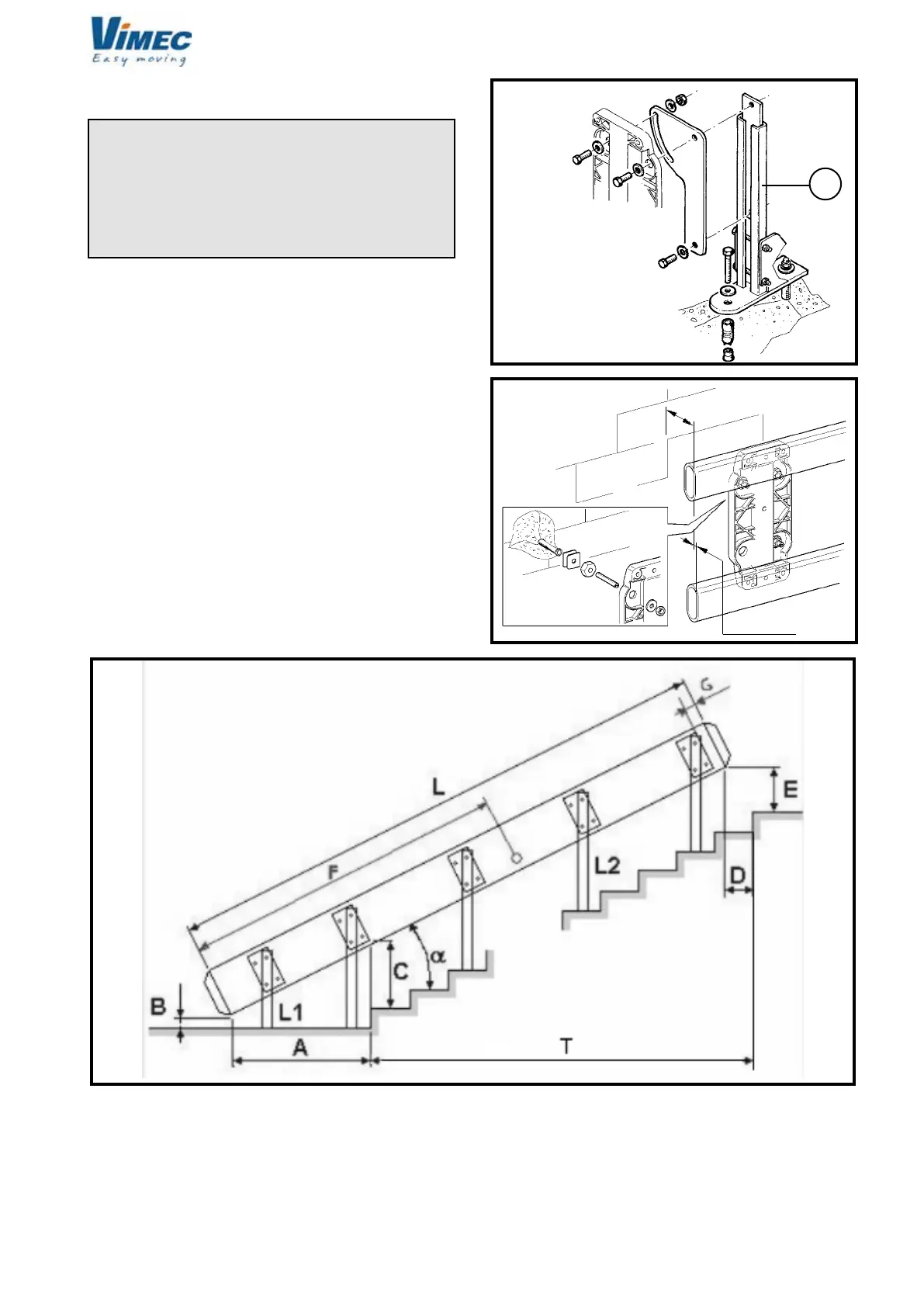
ASSEMBLY DRAWING AND RAIL
POSITIONING DIMENSIONS
FIG.8
CAPTIONS:
A: distance from lower rail side compared to the rst
raiser
B: distance between the lower rail side and the lower
landing oor
C: height under the rail
D: rail regression compared to the last raiser
E: distance between the lower rail side and the upper
landing oor
F: xing point of the cable holder chain
G: distance between the last upper connection and the
upper rail side
L: total rail length
L1: lower foot height
L2: height of feet placed on the steps
α : rail angle
T: Total steps
7512131