28
~ 130
c
d
b
a
e
7511131
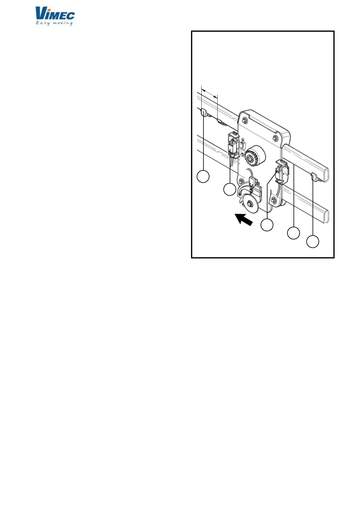
FIG.35
SN CARRIAGE CONFIGURATION
FRONT VIEW
MACHINE
ADVANCE
RISE
SIDE
DESCENT
SIDE
12) FINAL TESTING
Supply power to the system and perform the fol-
lowing functional checks:
- Load test:
- Load the stairlift with 1.1 times the rated load stated
on the nameplate.
- Send the stairlift up and down several times, checking
its stability on the rail.
- Drive the machine to the upper oor and place the
platform as to let the unloading of the wheelchair and
assemble the cam on the rail (Fig. 35/a), so that the
rise limit switch is pressed on (Fig. 35/b).
- Drive the machine to the lower oor and place the
platform as to let the unloading of the wheelchair and
assemble the cam on the rail (Fig. 35/c), so that the
descent limit switch operates (Fig. 35/d).
- Repeat the operation to check the operating of the
limit switch and over-run microswitches, making the
machine rise and descent.
- Lock the cams with the indicated cylindrical pin Ø4x30.
- Place the third cam (mechanical over-run device) with
the indicated cylindrical pin Ø4x30, on the rail rise side
paying attention to assemble it rotated 180° (Fig. 35/e).
- Preliminary checks
Perform the checks described in point 6.1 on page 8
of the Use and Maintenance Manual.
- Safety gear test
Test the safety gear as described in Section 9, point “d”.
(This test must be carried out with no load on the
stairlift).
- Check on xing of the rail
- Check that the rail is positioned in accordance with
the dimensions stated in the installation drawing (or
system layout) supplied with the stairlift.
- Check that all the xing screws of the connections
to the mounts or any expansion plugs are stable and
rmly tightened.
7512131