27
a
b
125
a
a
a
7511131
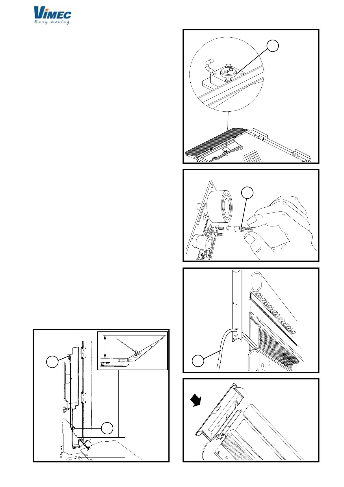
CLINOMETER RESET
The 1250x800 and 1050x900 standard platforms, and
other platforms upon customer’s request, are equipped
with a clinometer to check any footboard overloads (Fig.
31/a). Once the platform is completely installed, it must
be fully open in work mode.
To remove any possible clearances, a load of around
75-100 kg must be applied to the platform (it is sufcient
that an installer gets onto the footboard to remove such
clearance).
Now, reset the clinometer by making a jumper on the
rear of the card (Fig. 32/a); the sound of the card indi-
cates that the setting is in progress.
Press the “bell” push-button.
Remove the jumper.
The buzzer will indicate when the reset is completed.
9) CONNECTING THE ELECTRICAL SYSTEM
A wire comes out from the top end of the extruded
aluminium raceway on the rail (Fig. 33/a):
- blue wire 4x1, power supply.
Connect this wire as follows:
- Connect the 4x1 blue wire (Fig. 33/a) to the power sup-
ply mains using the circuit breaker installed previously
by the customer (cable gland + sheath).
- Fit the two rail cover guards (Fig. 34).
N.B.: The differential security breaker connected to the
mains power supply must be installed by the customer
before the system is installed
10) INSTALLATION CHECKS
- Check that all the stairlift’s microswitches are correctly
positioned, consulting the wiring diagrams provided.
11) FITTING THE CASINGS
- Fit all the casings provided with the stairlift.
FIG.34
FIG.33
FIG.30
FIG.31
FIG.32
7512131